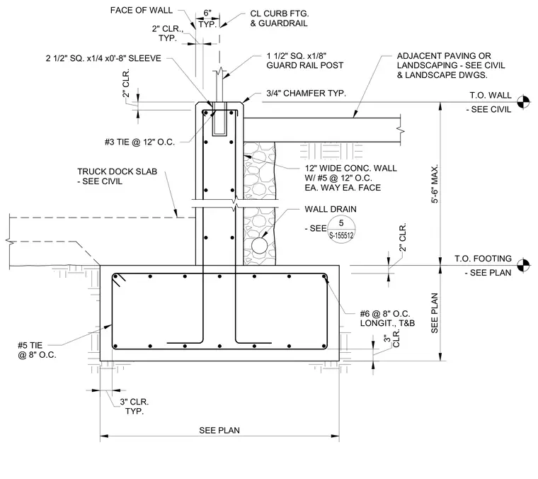
A twelve-inch-wide concrete retaining wall supported by a continuous concrete footing has a maximum wall height of five feet six inches. The wall is reinforced with number five reinforcing bars at twelve inches on center each way, each face, and features three-quarter-inch chamfers at the top corners. A one-and-a-half-inch square by one-eighth-inch guardrail post is anchored into a two-and-a-half-inch square by one-quarter-inch by zero-foot-eight-inch sleeve embedded in the top of the wall with two inches of clearance typical. The footing includes number three ties at twelve inches on center and number six longitudinal reinforcing bars at eight inches on center top and bottom, with three inches of concrete clearance typical. A wall drain connects to detail five on sheet S-155512, and the assembly interfaces with adjacent paving or landscaping and a truck dock slab sized per civil drawings.
TYP. 2" CLR., TYP. 6" CL CURB FTG. & GUARDRAIL FACE OF WALL 2 1/2" SQ. x1/4 x0'-8" SLEEVE 2" CLR. #3 TIE @ 12" O.C. TRUCK DOCK SLAB - SEE CIVIL #5 TIE @ 8" O.C. SEE PLAN #6 @ 8" O.C. LONGIT., T&B T.O. FOOTING - SEE PLAN 12" WIDE CONC. WALL W/ #5 @ 12" O.C. EA. WAY EA. FACE ADJACENT PAVING OR LANDSCAPING - SEE CIVIL & LANDSCAPE DWGS. 3/4" CHAMFER TYP. 1 1/2" SQ. x1/8" GUARD RAIL POST 2" CLR. TYP. 3" CLR. CLR. 3" SEE PLAN 5'-6" MAX. T.O. WALL - SEE CIVIL WALL DRAIN - SEE 5 S-155512
Members view this detail in full resolution, download the CAD files (SVG, PDF), and can adapt it in the built-in CAD editor — export DXF, DWG, or PDF.
Start membership