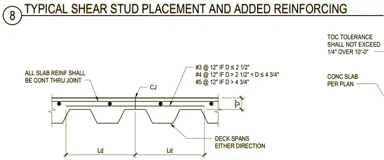
Typical shear stud placement and added reinforcement serve a concrete slab supported by metal deck spanning in either direction. The layout requires the first stud in the flute closest to the beam ends. All slab reinforcement remains continuous through the control joint. Added reinforcing bars are sized according to slab depth dimension D, utilizing number 3 bars at twelve inches spacing if depth is less than or equal to two and a half inches, number 4 bars at twelve inches if depth is between two and a half and four and three-quarter inches, and number 5 bars at twelve inches if depth exceeds four and three-quarter inches. Top of concrete tolerance shall not exceed one-quarter inch over ten feet.
DETERMINE STUD LAYOUT WITH FIRST STUD IN FLUTE CLOSEST TO BEAM ENDS ALL SLAB REINF SHALL BE CONT THRU JOINT #3 @ 12" IF D ≤2 1/2" #4 @ 12" IF D > 2 1/2" < D ≤4 3/4" #5 @ 12" IF D > 4 3/4" CJ DECK SPANS EITHER DIRECTION Ld Ld "D" CONC SLAB PER PLAN TOC TOLERANCE SHALL NOT EXCEED 1/4" OVER 10'-0" 8 TYPICAL SHEAR STUD PLACEMENT AND ADDED REINFORCING DETERMINE STUD LAYOUT WITH FIRST STUD IN FLUTE CLOSEST TO BEAM ENDS ALL SLAB REINF SHALL BE CONT THRU JOINT #3 @ 12" IF D ≤2 1/2" #4 @ 12" IF D > 2 1/2" < D ≤4 3/4" #5 @ 12" IF D > 4 3/4" CJ DECK SPANS EITHER DIRECTION Ld Ld "D" CONC SLAB PER PLAN TOC TOLERANCE SHALL NOT EXCEED 1/4" OVER 10'-0" 8 TYPICAL SHEAR STUD PLACEMENT AND ADDED REINFORCING
Members view this detail in full resolution, download the CAD files (SVG, PDF), and can adapt it in the built-in CAD editor — export DXF, DWG, or PDF.
Start membership