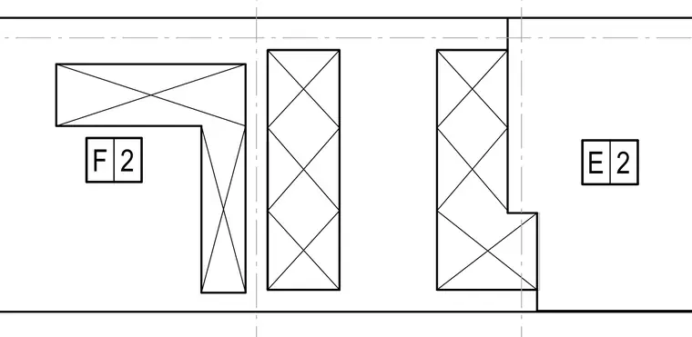
The drawing shows structural alignment markers and grid lines intersecting structural members with tags E and F. Grid lines run vertically through the assembly to coordinate member locations. Cross-hatched profiles indicate framing or support elements aligned with the grid coordinate system.
Members view this detail in full resolution, download the CAD files (SVG, PDF), and can adapt it in the built-in CAD editor — export DXF, DWG, or PDF.
Start membership