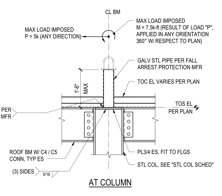
A galvanized steel pipe per fall arrest protection manufacturer requirements is supported by a steel column and roof beam assembly. The assembly includes a three-quarter-inch plate fitted to the steel column flanges and welded with five-sixteenth-inch welds on three sides. Roof beams connect to the column with C4 or C5 connections typical each side. The design accommodates a maximum imposed load P of 5 kips in any direction and a maximum imposed moment M of 7.5 kip-feet applied in any orientation 360 degrees with respect to the plan. Top of steel elevation and top of concrete elevation vary per plan with a maximum height of one foot six inches for the pipe.
PER PLAN TOS EL AT COLUMN MAX LOAD IMPOSED P = 5k (ANY DIRECTION) CL BM MAX LOAD IMPOSED M = 7.5k-ft (RESULT OF LOAD "P", APPLIED IN ANY ORIENTATION 360° W/ RESPECT TO PLAN) GALV STL PIPE PER FALL ARREST PROTECTION MFR TOC EL VARIES PER PLAN PL3/4 ES, FIT TO FLGS STL COL, SEE "STL COL SCHED" ROOF BM W/ C4 / C5 CONN, TYP ES (3) SIDES 5/16 WELD PER MFR MAX 1'-6"
Members view this detail in full resolution, download the CAD files (SVG, PDF), and can adapt it in the built-in CAD editor — export DXF, DWG, or PDF.
Start membership