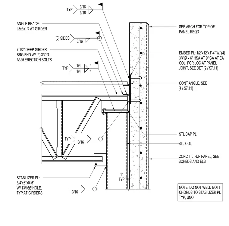
A concrete tilt-up panel connects to a steel column using an embed plate measuring half-inch by twelve inches by one foot four inches with four three-quarter-inch diameter by six-inch heavy stud anchors at nine-inch gauge at each column. A continuous angle and a steel cap plate tie the structural framing to the wall assembly. The seven-and-a-half-inch deep girder bears at its end with two three-quarter-inch diameter A325 erection bolts. An angle brace made of an L3x3x1/4 structural angle ties into the girder with typical three-sixteenth-inch welds. A stabilizer plate measuring three-quarters of an inch by six inches by six inches with a thirteen-sixteenth-inch diameter hole connects at the girders, left un-welded to the bottom chords unless noted otherwise.
CONC TILT-UP PANEL, SEE SCHEDS AND ELS SEE ARCH FOR TOP OF PANEL REQD STL COL STL CAP PL EMBED PL: 1/2"x12"x1'-4" W/ (4) 3/4"Ø x 6" HSA AT 9" GA AT EA COL. FOR LOC AT PANEL JOINT, SEE DET NOTE: DO NOT WELD BOTT CHORDS TO STABILIZER PL TYP, UNO STABILIZER PL: 3/4"x6"x0'-6" W/ 13/16Ø HOLE, TYP AT GIRDERS 7 1/2" DEEP GIRDER BRG END W/ (2) 3/4"Ø A325 ERECTION BOLTS ANGLE BRACE: L3x3x1/4 AT GIRDER TYP 1" 3/16 3/16 TYP 3/16 3/16 TYP 3/16 (3) SIDES 1/4 1/4 4 4 TYP CONT ANGLE, SEE / (4 S7.11) / (2 S7.11)
Members view this detail in full resolution, download the CAD files (SVG, PDF), and can adapt it in the built-in CAD editor — export DXF, DWG, or PDF.
Start membership