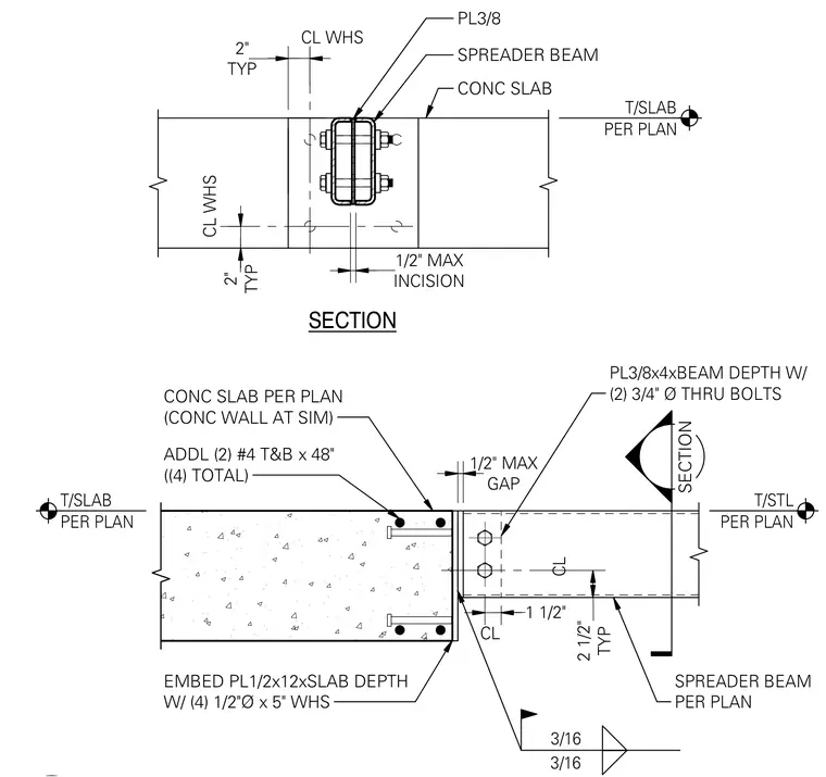
A spreader beam connects to a concrete slab or concrete wall per plan using a three-eighths-inch by four-inch plate sized to the beam depth with two three-quarter-inch-diameter through bolts. The concrete slab edge features an embedded half-inch by twelve-inch plate matching the slab depth, secured with four half-inch-diameter by five-inch welded headed studs. Additional reinforcing steel consists of two number four top and bottom bars measuring forty-eight inches in length for a total of four bars. A maximum one-half-inch gap and incision are maintained at the connection interface, with typical two-inch clearances to the centerline of the welded headed studs and two and a half inches to the spreader beam centerline.
T/SLAB PER PLAN T/STL PER PLAN T/SLAB PER PLAN 1 1/2" 3/16 3/16 EMBED PL1/2x12xSLAB DEPTH W/ (4) 1/2"Ø x 5" WHS ADDL (2) #4 T&B x 48" ((4) TOTAL) SECTION TYP 2" CONC SLAB CONC SLAB PER PLAN (CONC WALL AT SIM) CL WHS CL WHS TYP 2" SPREADER BEAM PL3/8 INCISION 1/2" MAX GAP 1/2" MAX PL3/8x4xBEAM DEPTH W/ (2) 3/4" Ø THRU BOLTS SPREADER BEAM PER PLAN CL CL SECTION TYP 2 1/2"
Members view this detail in full resolution, download the CAD files (SVG, PDF), and can adapt it in the built-in CAD editor — export DXF, DWG, or PDF.
Start membership