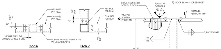
Channels frame into hollow structural section posts using a three-eighths-inch thick plate matching the channel width and one foot two inches long, secured with four three-quarter-inch diameter bolts between the channel and column. A one-half-inch maximum gap is maintained between the channel and column typical condition. A top of mechanical screen sits above the framing with bidder-designed screen and connections. Fillet welds of one-quarter-inch size connect the plate to the hollow structural section post.
C L PLAN C PLAN D CHANNEL PER PLAN HSS POST PER PLAN CHANNEL PER PLAN HSS POST PER PLAN PL3/8x CHANNEL WIDTH x 1'-2" W/ (4) 3/4"Ø BOLTS BTWN CHANNEL & COL 1/2" GAP MAX, TYP C L TYP 1 3/4" C L TYP 1 1/2" TYP 1 1/2" CHANNEL PER PLAN, TYP ROOF BEAM & SCREEN POST PLAN D AT CORNERS SCREEN PER PLAN T/MECH PLAN C 1/4 1/4 1/4 1/4 PLATE TO HSS BIDDER DESIGNED SCREEN & CONN
Members view this detail in full resolution, download the CAD files (SVG, PDF), and can adapt it in the built-in CAD editor — export DXF, DWG, or PDF.
Start membership