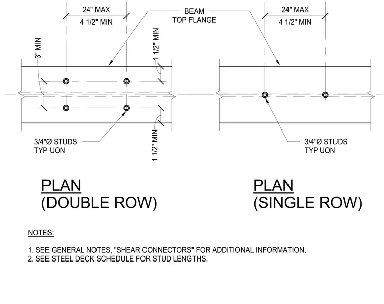
The assembly details shear stud placement configurations on a structural steel beam top flange with single and double row options. Three-quarter-inch diameter studs are typically installed unless otherwise noted, positioned with a four-and-a-half-inch minimum and twenty-four-inch maximum spacing along the beam length. The double row layout specifies a three-inch minimum transverse separation between stud rows, with edge distances maintaining a one-and-a-half-inch minimum from the flange edges. Stud lengths are determined by the steel deck schedule, and general notes direct further reference to project specifications for shear connector requirements.
PLAN (DOUBLE ROW) PLAN (SINGLE ROW) NOTES: 1. SEE GENERAL NOTES, "SHEAR CONNECTORS" FOR ADDITIONAL INFORMATION. 2. SEE STEEL DECK SCHEDULE FOR STUD LENGTHS. BEAM TOP FLANGE 3/4"Ø STUDS TYP UON 4 1/2" MIN 24" MAX 4 1/2" MIN 24" MAX 3/4"Ø STUDS TYP UON 1 1/2" MIN 1 1/2" MIN 3" MIN
Members view this detail in full resolution, download the CAD files (SVG, PDF), and can adapt it in the built-in CAD editor — export DXF, DWG, or PDF.
Start membership