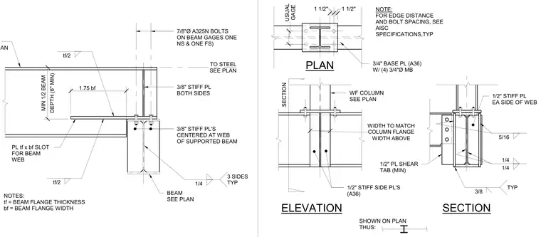
This connection detail features a wide flange column supported on a base plate secured with four three-quarter-inch diameter machine bolts. Half-inch A36 stiffener plates are welded to each side of the column web with typical fillet welds. Additional plate stiffeners centered at the web of the supported beam provide load transfer. Edge distance and bolt spacing must comply with AISC specifications.
SECTION SHOWN ON PLAN THUS: SECTION PLAN ELEVATION WF COLUMN SEE PLAN NOTE: FOR EDGE DISTANCE AND BOLT SPACING, SEE AISC SPECIFICATIONS,TYP 1/2" STIFF SIDE PL'S (A36) 1/2" PL SHEAR TAB (MIN) 3/4" BASE PL (A36) W/ (4) 3/4"Ø MB 1/2" STIFF PL EA SIDE OF WEB 3/8 TYP 1/4 1/4 5/16 WIDTH ABOVE WIDTH TO MATCH COLUMN FLANGE 1 1/2" 1 1/2" GAGE USUAL NOTES: tf = BEAM FLANGE THICKNESS bf = BEAM FLANGE WIDTH PL tf x bf SLOT FOR BEAM WEB BEAM SEE PLAN TO STEEL SEE PLAN SEE PLAN 3/8" STIFF PL'S CENTERED AT WEB OF SUPPORTED BEAM 3/8" STIFF PL BOTH SIDES 7/8"Ø A325N BOLTS ON BEAM GAGES ONE NS & ONE FS) 1.75 bf tf/2 DEPTH (6" MIN) MIN 1/2 BEAM 1/4 3 SIDES TYP tf/2
Members view this detail in full resolution, download the CAD files (SVG, PDF), and can adapt it in the built-in CAD editor — export DXF, DWG, or PDF.
Start membership