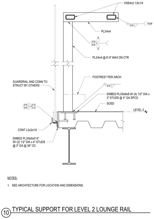
The assembly consists of an HSS 4x2 1/2x1/4 hollow structural section supported by three-quarter-inch by four-inch plates spaced at six-foot maximum on center. A footrest per architecture connects to the lower portion of the vertical support. The base plate is a three-eighths by eight by eight-inch embed plate secured with four half-inch diameter by three-inch studs at four-inch gauge spacing. A continuous two by two by one-quarter-inch angle is attached to the edge of the slab using an embed plate measuring three-eighths by five by six inches with two half-inch diameter by four-inch studs at three-inch gauge and thirty-six-inch on-center spacing. Fillet welds of three-sixteenths inch secure the steel connections throughout the assembly.
HSS4x2 1/2x1/4 TYP 3/16 PL3/4x4 3/16 3/16 PL3/4x4 @ 6'-0" MAX ON CTR 3/16 EMBED PL3/8x8x8 W/ (4) 1/2" DIA x 3" STUDS @ 4" GA SPCG SOSD LEVEL 2 EMBED PL3/8x5x0'-6" W/ (2) 1/2" DIA x 4" STUDS @ 3" GA @ 36" OC 3-12 3-12 3/16 3/16 CONT L2x2x1/4 GUARDRAIL AND CONN TO STRUCT BY OTHERS NOTES: 1. SEE ARCHITECTURE FOR LOCATION AND DIMENSIONS. G G FOOTREST PER ARCH 10 TYPICAL SUPPORT FOR LEVEL 2 LOUNGE RAIL
Members view this detail in full resolution, download the CAD files (SVG, PDF), and can adapt it in the built-in CAD editor — export DXF, DWG, or PDF.
Start membership