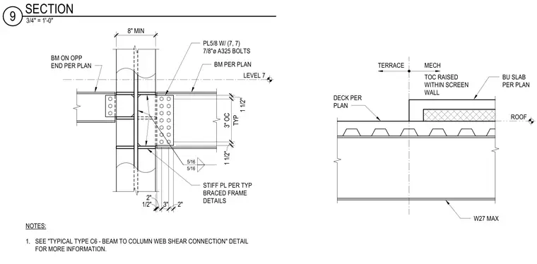
A steel beam connects to a column web using a five-eighths-inch thick plate secured with fourteen seven-eighths-inch diameter A325 bolts spaced at three inches on center vertically. Stiffener plates welded with five-sixteenths-inch fillet welds align horizontally with the beam flanges. A beam on the opposite end frames into the column flange per plan. At the adjacent roof and terrace area, a built-up slab bears on metal deck over a W27 maximum beam, with the top of concrete raised within a screen wall.
W27 MAX BU SLAB PER PLAN DECK PER PLAN TERRACE MECH TOC RAISED WITHIN SCREEN WALL ROOF 8" MIN 5/16 5/16 2" 3" 2" 1/2" 1 1/2" TYP 3" OC 1 1/2" PL5/8 W/ (7, 7) 7/8"ø A325 BOLTS BM PER PLAN BM ON OPP END PER PLAN STIFF PL PER TYP BRACED FRAME DETAILS NOTES: 1. SEE "TYPICAL TYPE C6 - BEAM TO COLUMN WEB SHEAR CONNECTION" DETAIL FOR MORE INFORMATION. LEVEL 7 3/4" = 1'-0" 9 SECTION
Members view this detail in full resolution, download the CAD files (SVG, PDF), and can adapt it in the built-in CAD editor — export DXF, DWG, or PDF.
Start membership