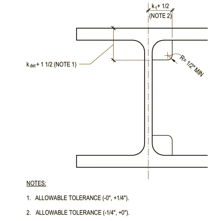
This structural steel detail defines the configuration for a continuity plate clip at a wide flange member. The corner clip features a minimum radius of one-half inch. Dimensional callouts indicate placement tolerances including a variable dimension based on the detailing distance k plus one and one-half inches with an allowable tolerance of minus zero and plus one-quarter inch, and another dimension based on k plus one-half inch with an allowable tolerance of minus one-quarter inch and plus zero.
NOTES: 1. ALLOWABLE TOLERANCE (-0", +1/4"). 2. ALLOWABLE TOLERANCE (-1/4", +0"). 3 1/2" 2 5/8" k + 1/2 (NOTE 2) k + 1 1/2 (NOTE 1) det 1 R= 1/2" MIN NOTES: 1. ALLOWABLE TOLERANCE (-0", +1/4"). 2. ALLOWABLE TOLERANCE (-1/4", +0"). 3 1/2" 2 5/8" k + 1/2 (NOTE 2) k + 1 1/2 (NOTE 1) det 1 R= 1/2" MIN
Members view this detail in full resolution, download the CAD files (SVG, PDF), and can adapt it in the built-in CAD editor — export DXF, DWG, or PDF.
Start membership