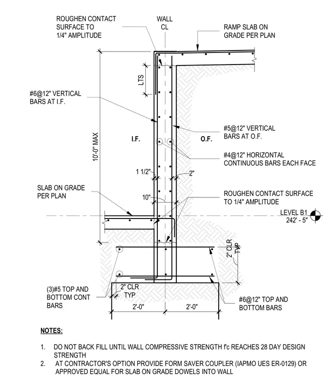
A concrete retaining wall connects to a ramp slab on grade and footing, featuring a ten-foot maximum wall height and a ten-inch nominal wall thickness. The footing is reinforced with three number five top and bottom continuous bars alongside number six bars at twelve inches spacing, maintaining two-inch typical clear cover. The wall contains number six vertical bars at the inside face spaced at twelve inches and number five vertical bars at the outside face spaced at twelve inches, with number four horizontal continuous bars on each face. Contact surfaces at the slab joints are roughened to a quarter-inch amplitude. Dowels from the slab on grade tie into the wall, with an optional form saver coupler permitted per the notes.
LEVEL B1 242' - 5" TYP 2" CLR TYP 2" CLR 2'-0" 2'-0" #6@12" TOP AND BOTTOM BARS ROUGHEN CONTACT SURFACE TO 1/4" AMPLITUDE #4@12" HORIZONTAL CONTINUOUS BARS EACH FACE #5@12" VERTICAL BARS AT O.F. RAMP SLAB ON GRADE PER PLAN WALL CL #6@12" VERTICAL BARS AT I.F. SLAB ON GRADE PER PLAN (3)#5 TOP AND BOTTOM CONT BARS ROUGHEN CONTACT SURFACE TO 1/4" AMPLITUDE I.F. O.F. 10" 1 1/2" 2" LTS 10'-0'' MAX NOTES: 1. DO NOT BACK FILL UNTIL WALL COMPRESSIVE STRENGTH f'c REACHES 28 DAY DESIGN STRENGTH 2. AT CONTRACTOR'S OPTION PROVIDE FORM SAVER COUPLER (IAPMO UES ER-0129) OR APPROVED EQUAL FOR SLAB ON GRADE DOWELS INTO WALL
Members view this detail in full resolution, download the CAD files (SVG, PDF), and can adapt it in the built-in CAD editor — export DXF, DWG, or PDF.
Start membership