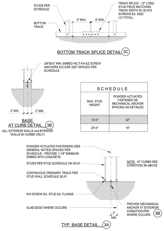
The typical base detail anchors a continuous ordinary track to a concrete slab or curb using powder-actuated fasteners or mechanical anchors spaced per schedule with a one-and-one-eighth-inch minimum embedment. Steel studs attach to the bottom track with a number ten screw at each stud flange. The base at curb detail features a three-eighths-inch-diameter by three-inch minimum embedment Hilti KH-EZ screw anchor complying with ICC-ESR 3027, centered on a minimum two-inch edge distance. The bottom track splice detail utilizes a twelve-inch-long stud piece matching the track width, fastened with six number ten screws on each side for a total of twelve screws, positioned nine inches maximum from the joint. An accompanying schedule provides maximum stud heights of twelve feet and twenty feet corresponding to powder-actuated fastener or mechanical anchor spacings of thirty-two inches and sixteen inches respectively.
3A TYP. BASE DETAIL__ BASE AT CURB DETAIL__ 3B BOTTOM TRACK SPLICE DETAIL 3C TRACK SPLICE - 12" LONG STUD PIECE MATCHING TRACK WIDTH W/ (6) #10 SCREWS EA. SIDE (12 TOTAL) STUDS PER SCHEDULE BOTTOM TRACK 9" MAX. 9" MAX. 2" MIN. 3/8"Øx3" MIN. EMBED HILTI KH-EZ SCREW ANCHORS ICC-ESR 3027 SPACED PER SCHEDULE MAX. STUD HEIGHT POWDER ACTUATED FASTENER OR MECHANICAL ANCHOR SPACING AS DETAILED 12'-0" 20'-0" 32" 16" S C H E D U L E NOTE: AT CURBS SEE CONDITION 3B ABOVE POWDER ACTUATED FASTENERS (SEE GENERAL NOTES) SPACED PER SCHEDULE - PROVIDE 1-1/8" MINIMUM EMBED INTO CONCRETE STUDS PER STUD SCHEDULE ON S0.91 CONTINUOUS ORDINARY TRACK PER STUD WALL SCHEDULE S0.91 #10 SCREW EA. STUD EA. FLANGE SLAB EDGE WHERE OCCURS 2" MIN. (ALL EXTERIOR WALLS and INTERIOR WALLS W/ CURBS ONLY) PROVIDE MECHANICAL ANCHOR AT EXTERIOR CONDITION PER WHERE OCCURS 3B MIN. 2"
Members view this detail in full resolution, download the CAD files (SVG, PDF), and can adapt it in the built-in CAD editor — export DXF, DWG, or PDF.
Start membership