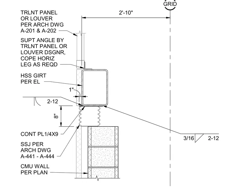
A hollow structural section girt connects to a concrete masonry unit wall below, positioned two feet ten inches from the grid line. A continuous one-quarter by nine-inch steel plate welded with a three-sixteenth-inch fillet weld sits beneath the hollow structural section girt. A structural silicone joint per architectural drawings bridges the gap between the continuous plate and the top of the concrete masonry unit wall. A translucent panel or louver with a support angle whose horizontal leg is coped as required bears on the assembly above.
21 GRID CONT PL1/4X9 3/16 2-12 HSS GIRT PER EL 8" 2'-10" 1" SSJ PER ARCH DWG A-441 - A-444 CMU WALL PER PLAN 2-12 TRLNT PANEL OR LOUVER PER ARCH DWG A-201 & A-202 SUPT ANGLE BY TRLNT PANEL OR LOUVER DSGNR, COPE HORIZ LEG AS REQD
Members view this detail in full resolution, download the CAD files (SVG, PDF), and can adapt it in the built-in CAD editor — export DXF, DWG, or PDF.
Start membership