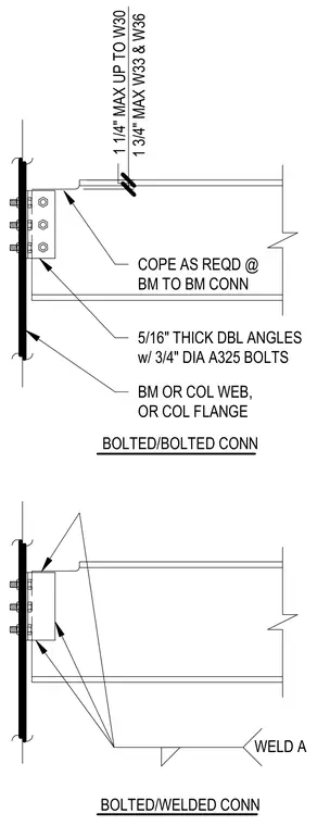
A supported steel beam connects to a supporting beam or column web or flange using five-sixteenth-inch thick double angles with three-quarter-inch diameter A325 bolts. The supported beam flange features a cope as required for beam-to-beam connections, maintaining one-and-a-quarter-inch maximum clearance for up to W30 shapes and one-and-three-quarter-inch maximum clearance for W33 and W36 shapes. The top diagram shows a fully bolted configuration while the bottom diagram shows a bolted and welded configuration using weld A.
1 3/4" MAX W33 & W36 COPE AS REQD @ BM TO BM CONN 5/16" THICK DBL ANGLES w/ 3/4" DIA A325 BOLTS BM OR COL WEB, OR COL FLANGE 1 1/4" MAX UP TO W30 BOLTED/BOLTED CONN BOLTED/WELDED CONN WELD A
Members view this detail in full resolution, download the CAD files (SVG, PDF), and can adapt it in the built-in CAD editor — export DXF, DWG, or PDF.
Start membership