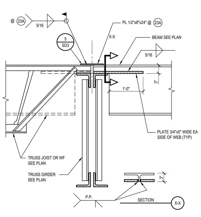
A truss joist or wide flange beam is supported by a truss girder. The supported member connects to the girder using 3/4-inch by 5-inch wide plates attached to each side of the web, extending 1 foot from the connection point. A 1/2-inch by 8-inch by 24-inch plate is positioned at the top of the connection, secured with 5/16-inch fillet welds. A 3-inch clearance exists between the top of the supported member and the top plate. Section X-X defines the plate configuration relative to the girder web.
22 TRUSS TO TRUSS @ BEAM N.T.S. 16-SD4(12) BEAM SEE PLAN 1'-0" PLATE 3/4"x5" WIDE EA SIDE OF WEB (TYP) 3" TRUSS JOIST OR WF SEE PLAN TRUSS GIRDER SEE PLAN 5/16 5 SD3 PL 1/2"x8"x24" @ 23A 5/16 @ 23A X-X X-X SECTION 3" P.P.
Members view this detail in full resolution, download the CAD files (SVG, PDF), and can adapt it in the built-in CAD editor — export DXF, DWG, or PDF.
Start membership