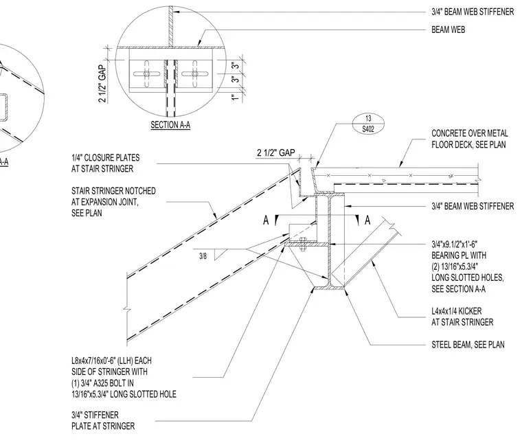
A stair stringer is notched at a two-and-a-half-inch expansion joint and framed into a structural steel beam. The steel beam supports a concrete slab over a metal floor deck and features three-quarter-inch web stiffeners along with a three-quarter-inch by nine-and-a-half-inch by one-foot-six-inch bearing plate containing two thirteen-sixteenths by five-and-three-quarter-inch long slotted holes. An L8x4x7/16 by zero-foot-six-inch angle with long legs horizontal is attached to each side of the stringer using one three-quarter-inch A325 bolt in a thirteen-sixteenths by five-and-three-quarter-inch long slotted hole. Additional components include a three-quarter-inch stiffener plate at the stringer, quarter-inch closure plates at the stair stringer, and an L4x4x1/4 kicker angle supporting the stringer assembly.
SECTION A-A A A STEEL BEAM, SEE PLAN CONCRETE OVER METAL FLOOR DECK, SEE PLAN STAIR STRINGER NOTCHED AT EXPANSION JOINT, 3/8 3/4" BEAM WEB STIFFENER 3/4" STIFFENER PLATE AT STRINGER L8x4x7/16x0'-6" (LLH) EACH SIDE OF STRINGER WITH (1) 3/4" A325 BOLT IN 13/16"x5.3/4" LONG SLOTTED HOLE 3/4"x9.1/2"x1'-6" BEARING PL WITH (2) 13/16"x5.3/4" LONG SLOTTED HOLES, SEE SECTION A-A L4x4x1/4 KICKER AT STAIR STRINGER SECTION A-A BEAM WEB 3/4" BEAM WEB STIFFENER 1/4" CLOSURE PLATES AT STAIR STRINGER SEE PLAN 13 S402 2 1/2" GAP 2 1/2" GAP 3" 3" 1"
Members view this detail in full resolution, download the CAD files (SVG, PDF), and can adapt it in the built-in CAD editor — export DXF, DWG, or PDF.
Start membership