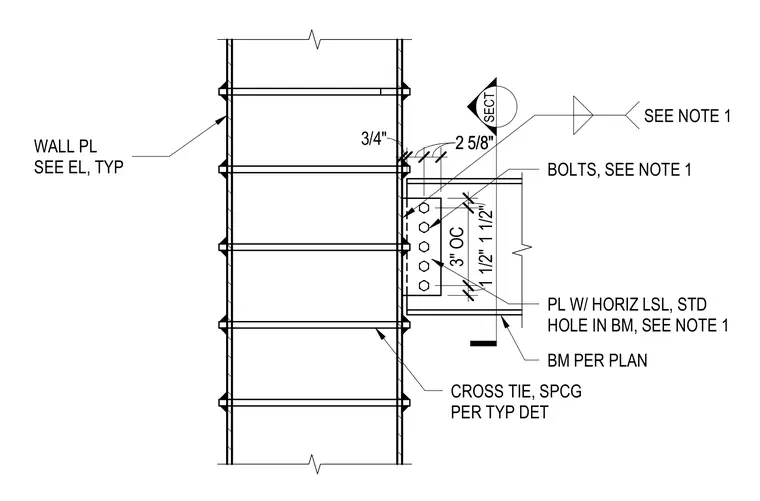
A beam per plan connects to a vertical wall plate with horizontal slotted holes and standard holes in the beam. Five vertical bolts secure the connection with an edge distance of one and one-half inches and a three-inch on-center spacing. The assembly includes wall plates sized per elevation and cross ties spaced according to typical wall plate details. All bolt sizes, connections, and associated notes are governed by general drawing notes.
SECT CROSS TIE, SPCG PER TYP DET WALL PL SEE EL, TYP PL W/ HORIZ LSL, STD HOLE IN BM, SEE NOTE 1 BOLTS, SEE NOTE 1 BM PER PLAN 3/4" 2 5/8" 2 5/8" SEE NOTE 1 1 1/2" 3" OC 1 1/2"
Members view this detail in full resolution, download the CAD files (SVG, PDF), and can adapt it in the built-in CAD editor — export DXF, DWG, or PDF.
Start membership