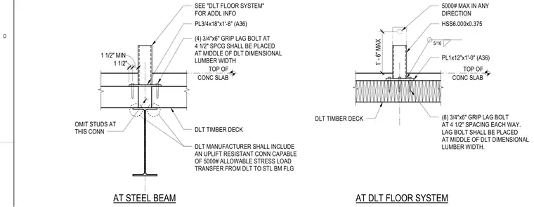
An uplift resistant connection transfers load between a dowel laminated timber deck and the supporting steel beam or floor system using a hollow structural section anchor. The assembly consists of an HSS6.000x0.375 structural section welded with a five-sixteenths fillet weld to an ASTM A36 steel plate, sized three-quarters by eighteen inches by one foot six inches at steel beams and one by twelve inches by one foot at timber decks. Four three-quarter-inch by six-inch grip lag bolts at four-and-a-half-inch spacing secure the plate at steel beams, while eight lag bolts at four-and-a-half-inch spacing each way secure the plate at the dowel laminated timber floor system. Shear studs are omitted at this connection to accommodate the embedded steel plate and concrete slab topping. The manufacturer provides an uplift resistant connection capable of a five-thousand-pound allowable stress load transfer from the timber deck to the steel beam flange.
AT STEEL BEAM (4) 3/4"x6" GRIP LAG BOLT AT 4 1/2" SPCG SHALL BE PLACED AT MIDDLE OF DLT DIMENSIONAL LUMBER WIDTH PL3/4x18"x1'-6" (A36) OMIT STUDS AT THIS CONN 1 1/2" 1 1/2" MIN SEE "DLT FLOOR SYSTEM" FOR ADDL INFO DLT TIMBER DECK DLT MANUFACTURER SHALL INCLUDE AN UPLIFT RESISTANT CONN CAPABLE OF 5000# ALLOWABLE STRESS LOAD TRANSFER FROM DLT TO STL BM FLG CONC SLAB TOP OF AT DLT FLOOR SYSTEM (8) 3/4"x6" GRIP LAG BOLT AT 4 1/2" SPACING EACH WAY. LAG BOLT SHALL BE PLACED AT MIDDLE OF DLT DIMENSIONAL LUMBER WIDTH. PL1x12"x1'-0" (A36) DLT TIMBER DECK HSS6.000x0.375 CONC SLAB TOP OF 5000# MAX IN ANY DIRECTION 1' - 6" MAX 5/16 D
Members view this detail in full resolution, download the CAD files (SVG, PDF), and can adapt it in the built-in CAD editor — export DXF, DWG, or PDF.
Start membership