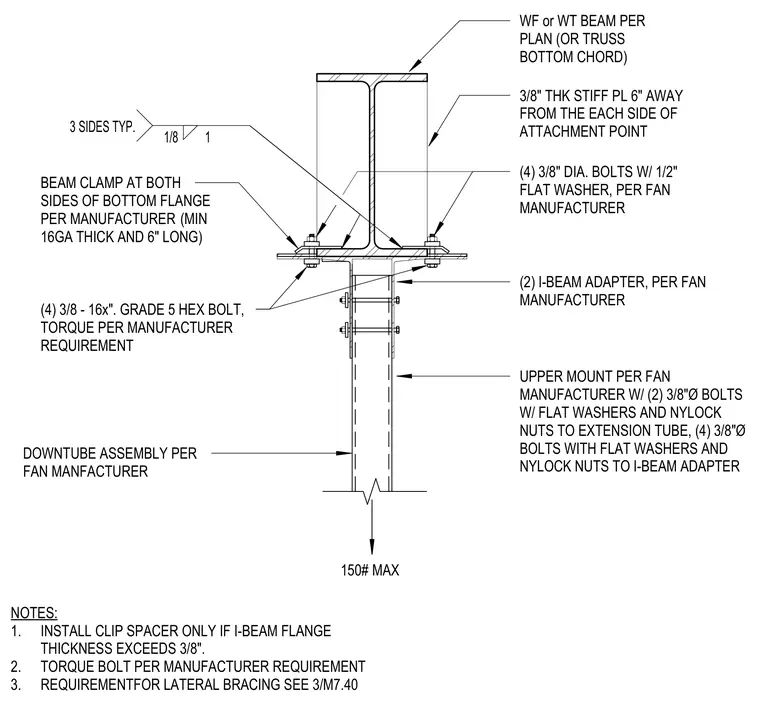
A ceiling fan downtube assembly hangs from a wide-flange beam or truss bottom chord using dual I-beam adapters and manufacturer-specified beam clamps on both sides of the bottom flange. The beam clamps measure a minimum of sixteen gauge thick and six inches long, secured by four three-eighths-inch diameter bolts with half-inch flat washers. Four three-eighths-inch by sixteen-inch Grade 5 hex bolts connect the I-beam adapters to the upper mount per the manufacturer's torque requirements. An upper mount attaches to the extension tube using two three-eighths-inch diameter bolts with flat washers and nylock nuts. Three-eighths-inch thick stiffener plates are welded six inches away from each side of the attachment point with a one-eighth-inch fillet weld on three sides. A clip spacer is installed only if the I-beam flange thickness exceeds three-eighths of an inch.
UPPER MOUNT PER FAN MANUFACTURER W/ (2) 3/8"Ø BOLTS W/ FLAT WASHERS AND NYLOCK NUTS TO EXTENSION TUBE, (4) 3/8"Ø BOLTS WITH FLAT WASHERS AND NYLOCK NUTS TO I-BEAM ADAPTER 1/8 1 3 SIDES TYP. BEAM CLAMP AT BOTH SIDES OF BOTTOM FLANGE PER MANUFACTURER (MIN 16GA THICK AND 6" LONG) WF or WT BEAM PER PLAN (OR TRUSS BOTTOM CHORD) (4) 3/8" DIA. BOLTS W/ 1/2" FLAT WASHER, PER FAN MANUFACTURER (4) 3/8 - 16x". GRADE 5 HEX BOLT, TORQUE PER MANUFACTURER REQUIREMENT (2) I-BEAM ADAPTER, PER FAN MANUFACTURER DOWNTUBE ASSEMBLY PER FAN MANFACTURER NOTES: 1. 2. 3. INSTALL CLIP SPACER ONLY IF I-BEAM FLANGE THICKNESS EXCEEDS 3/8". TORQUE BOLT PER MANUFACTURER REQUIREMENT REQUIREMENTFOR LATERAL BRACING SEE 3/M7.40 150# MAX 3/8" THK STIFF PL 6" AWAY FROM THE EACH SIDE OF ATTACHMENT POINT
Members view this detail in full resolution, download the CAD files (SVG, PDF), and can adapt it in the built-in CAD editor — export DXF, DWG, or PDF.
Start membership