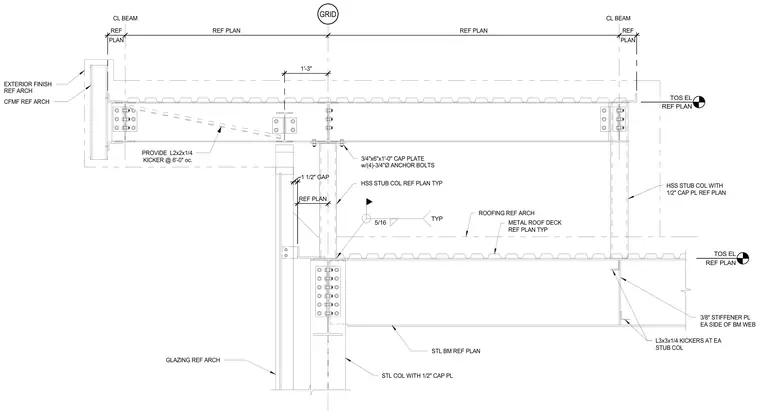
A structural steel framing connection consists of a hollow structural section stub column topped with a three-quarter inch by six-inch by one-foot-zero-inch cap plate secured by four three-quarter inch diameter anchor bolts. Beams frame into the assembly with three-eighth inch stiffener plates on each side of the beam web and are stabilized by angle kickers sized two-by-two by one-quarter inches provided at six feet on center. A metal roof deck spans across the steel beams, maintaining a one and one-half inch gap alongside cold-formed metal framing and exterior finishes referenced from architectural drawings. Five-sixteenth inch typical fillet welds connect structural elements where specified.
GRID GLAZING REF ARCH PLAN REF REF PLAN REF PLAN PLAN REF TOS EL REF PLAN STL BM REF PLAN CL BEAM CL BEAM METAL ROOF DECK REF PLAN TYP ROOFING REF ARCH REF PLAN CFMF REF ARCH EXTERIOR FINISH REF ARCH STL COL WITH 1/2" CAP PL HSS STUB COL REF PLAN TYP 3/4"x6"x1'-0" CAP PLATE w/(4)-3/4"Ø ANCHOR BOLTS HSS STUB COL WITH 1/2" CAP PL REF PLAN 5/16 TYP 3/8" STIFFENER PL EA SIDE OF BM WEB L3x3x1/4 KICKERS AT EA STUB COL TOS EL REF PLAN 1 1/2" GAP 1'-3" PROVIDE L2x2x1/4 KICKER @ 6'-0" oc.
Members view this detail in full resolution, download the CAD files (SVG, PDF), and can adapt it in the built-in CAD editor — export DXF, DWG, or PDF.
Start membership