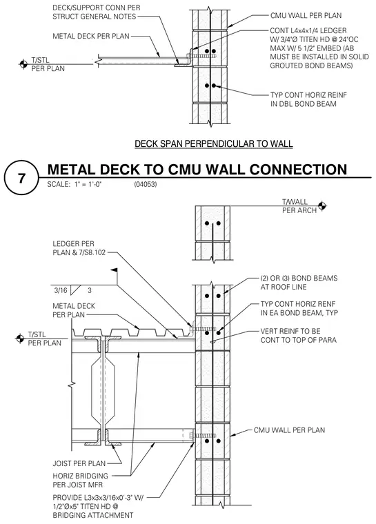
A metal roof deck bears on a concrete masonry unit wall via a continuous angle ledger secured with three-quarter-inch diameter masonry anchor bolts at twenty-four inches on center with five-and-a-half-inch embedment into solid grouted bond beams. The top of the concrete masonry wall includes double bond beams with continuous horizontal reinforcement and vertical reinforcement continuing to the top of the parapet. Open-web steel joists frame into or alongside the wall with horizontal bridging provided by the joist manufacturer using three-by-three-by-three-sixteenth-inch angles fastened with half-inch diameter by five-inch masonry screws. Deck support and deck span details follow structural general notes and architectural elevations for top-of-wall and top-of-steel elevations.
CMU WALL PER PLAN (2) OR (3) BOND BEAMS AT ROOF LINE TYP CONT HORIZ RENF IN EA BOND BEAM, TYP JOIST PER PLAN LEDGER PER PLAN & METAL DECK PER PLAN T/STL PER PLAN T/WALL PER ARCH VERT REINF TO BE CONT TO TOP OF PARA 3/16 3 HORIZ BRIDGING PER JOIST MFR PROVIDE L3x3x3/16x0'-3" W/ 1/2"Øx5" TITEN HD @ BRIDGING ATTACHMENT 7/S8.102 TYP CONT HORIZ REINF IN DBL BOND BEAM CMU WALL PER PLAN METAL DECK PER PLAN DECK/SUPPORT CONN PER STRUCT GENERAL NOTES DECK SPAN PERPENDICULAR TO WALL T/STL PER PLAN CONT L4x4x1/4 LEDGER W/ 3/4"Ø TITEN HD @ 24"OC MAX W/ 5 1/2" EMBED (AB MUST BE INSTALLED IN SOLID GROUTED BOND BEAMS) SCALE: 1" = 1'-0" 7 METAL DECK TO CMU WALL CONNECTION (04053)
Members view this detail in full resolution, download the CAD files (SVG, PDF), and can adapt it in the built-in CAD editor — export DXF, DWG, or PDF.
Start membership