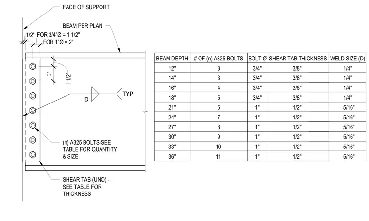
A standard single plate shear tab connection frames a steel beam to a support member, accompanied by a design standard table. The shear tab is welded to the face of support with a fillet weld sized per the accompanying schedule and bolted to the beam web using ASTM A325 high-strength bolts. The accompanying table provides sizing requirements based on beam depth, specifying the number and diameter of bolts, shear tab thickness, and fillet weld size ranging from twelve to thirty-six inches. Edge distances are specified as one and one-half inches for three-quarter inch diameter bolts and two inches for one inch diameter bolts, with a standard three-inch vertical bolt spacing.
BEAM DEPTH # OF (n) A325 BOLTS 12" 3 14" 3 16" 4 18" 5 21" 6 24" 7 27" 8 30" 9 FACE OF SUPPORT BEAM PER PLAN SHEAR TAB (UNO) - SEE TABLE FOR THICKNESS (n) A325 BOLTS-SEE TABLE FOR QUANTITY & SIZE 1/2" D TYP BOLT Ø SHEAR TAB THICKNESS 3/8" 3/8" 3/8" 3/8" 1/2" 10 11 33" 36" 3/4" 3/4" 3/4" 3/4" 1" 1" 1" 1" 1" 1" FOR 1"Ø = 2" FOR 3/4"Ø = 1 1/2" 3" 1 1/2" 1/2" 1/2" 1/2" 1/2" 1/2" WELD SIZE (D) 1/4" 1/4" 1/4" 1/4" 5/16" 5/16" 5/16" 5/16" 5/16" 5/16"
Members view this detail in full resolution, download the CAD files (SVG, PDF), and can adapt it in the built-in CAD editor — export DXF, DWG, or PDF.
Start membership