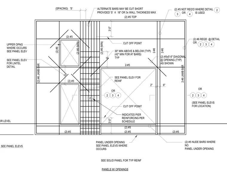
This structural drawing details the typical reinforcing steel layout for concrete wall panels featuring window or door openings. The elevation shows vertical and horizontal wall reinforcement, two number six jamb bars framing the sides of openings, and two number five by five-foot diagonal bars placed at each corner of an opening. Additional requirements include two number five bars extending thirty inches minimum above and below openings, alternating vertical bars spaced per panel elevations or maximum eighteen inches, and specific pier reinforcing per schedule. Lintel and sill conditions are detailed with specified bar counts and sizes for upper and lower openings.
SEE PANEL ELEVS (SPACING) 'S' O 3'-0" 3'-0" 2" 6" SEE SOLID PANEL FOR TYP REINF PANELS W/ OPENINGS FLOOR LEVEL ALTERNATE BARS MAY BE CUT SHORT PROVIDED 'S' ≤ 18" OR 3x WALL THICKNESS MAX (2) #6 JAMB BAR 2-#6 JAMB BAR (2) #6 (2) #6 (MIN) (2) #5 NOT REQ'D WHERE DETAIL OR IS USED CUT OFF POINT (2) #5x5'-0" DIAGONAL @ OPENING (TYP) AS SHOWN 2-#5 2-#6 2-#6 (2) #5 (2) #5 30" MIN ABOVE & BELOW (TYP) (42" MIN FOR #7 BARS) TYP (2) #6 REQD @ DETAIL OR SEE PANEL ELEV FOR REINF CUT OFF POINT PANEL UNDER OPENING SEE PANEL ELEVS WHERE OCCURS (2) #5 NUDE BARS WHERE NO PANEL UNDER OPENING OR (SEE PANEL ELEVS FOR LOCATION) (2) #5 (2) #5 (2) #5 (2) #5 TOP (2) #6 (MIN) OR (2) #5 UPPER OPNG WHERE OCCURS SEE PANEL ELEV SEE PANEL ELEV FOR LINTEL DETAIL O 2 3 4 2 3 4 2 3 4 2 3 4 2 INDICATES PIER REINFORCING PER SCHEDULE
Members view this detail in full resolution, download the CAD files (SVG, PDF), and can adapt it in the built-in CAD editor — export DXF, DWG, or PDF.
Start membership