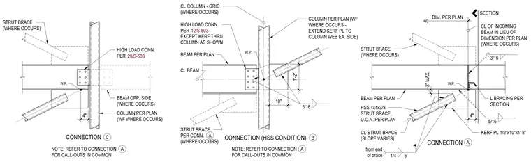
Three structural steel connection details illustrate column-to-beam junctions with hollow structural section strut braces and gusset plates. Connection A features an HSS 4x4x3/8 strut brace framing into a kerf plate measuring 1/2 inch by 10 inches by 1 foot 8 inches, welded with fillet welds to the incoming beam and column web. Connection B and Connection C show high-load connections at wide-flange columns with intersecting strut braces detailed per plan. Working points and centerline dimensions establish spatial positioning for the framing members and braces.
CONNECTION CONNECTION (HSS CONDITION) CONNECTION W.P. STRUT BRACE (WHERE OCCURS) BEAM PER PLAN HSS 4x4x3/8 STRUT BRACE, U.O.N. PER PLAN KERF PL 1/2"x10"x1'-8" CL COLUMN - GRID (WHERE OCCURS) BEAM PER PLAN COLUMN PER PLAN (WF WHERE OCCURS - EXTEND KERF PL TO COLUMN WEB EA. SIDE) CL OF INCOMING BEAM IN LIEU OF DIMENSION PER PLAN (WHERE OCCURS) DIM. PER PLAN CL STRUT BRACE (SLOPE VARIES) L BRACING PER SECTION NOTE: REFER TO CONNECTION FOR CALL-OUTS IN COMMON NOTE: REFER TO CONNECTION FOR CALL-OUTS IN COMMON HIGH LOAD CONN. PER EXCEPT KERF THRU COLUMN AS SHOWN STRUT BRACE PER CONN. (WHERE OCCURS) CL BEAM SECTION 1/4 6 from end of brace 5/16 3/16 A A B A 5/16 A C W.P. STRUT BRACE (WHERE OCCURS) COLUMN PER PLAN (WF WHERE OCCURS) HIGH LOAD CONN. PER BEAM OPP. SIDE (WHERE OCCURS) W.P. 4" 4" 2" MAX. 10" 1'-2" 12/S-503 29/S-503
Members view this detail in full resolution, download the CAD files (SVG, PDF), and can adapt it in the built-in CAD editor — export DXF, DWG, or PDF.
Start membership