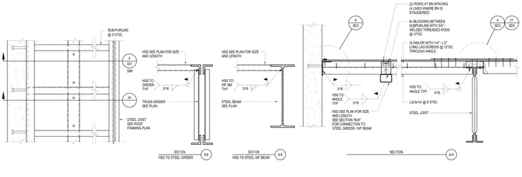
Hollow structural section struts connect to wide-flange steel beams and truss girders using three-sixteenth-inch typical fillet welds, with sizing determined per the structural plan. A three-by-four wood blocking sits between sub-purlins spaced at two feet on center, secured by three-quarter-inch diameter welded threaded rods at twelve inches on center. A three-by wood nailer fastens with one-quarter-inch diameter by two-inch long lag screws at twelve inches on center through a three-by-three by one-quarter-inch structural angle spaced at eight feet on center. Steel joists and sub-purlins tie into the framing assembly as indicated on the roof framing plan.
A-A SECTION B-B SECTION HSS TO STEEL WF BEAM B-B SECTION HSS TO STEEL GIRDER 6x BLOCKING BETWEEN SUBPURLINS WITH 3/4" ∅ WELDED THREADED RODS @ 12"OC 3x NAILER WITH 1/4" ∅ x 2" LONG LAG SCREWS @ 12"OC THROUGH ANGLE L3x3x1/4 @ 8'-0"OC HSS SEE PLAN FOR SIZE AND LENGTH SEE SECTION "B-B" FOR CONNECTION TO STEEL GIRDER / WF BEAM 4 SD3 21 SD3 3/16 STEEL JOIST 3/16 HSS TO ANGLE TYP 3/16 HSS TO ANGLE TYP (2) ROWS AT BN SPACING (4 LINES WHERE BN IS STAGGERED) 8 SD3 SUB-PURLINS @ 2'-0"OC 8 SD3 SIM AA - STEEL JOIST SEE ROOF FRAMING PLAN 3/16 HSS TO WF BM TYP HSS SEE PLAN FOR SIZE AND LENGTH STEEL BEAM SEE PLAN 3/16 HSS TO GIRDER TYP HSS SEE PLAN FOR SIZE AND LENGTH TRUSS GIRDER SEE PLAN
Members view this detail in full resolution, download the CAD files (SVG, PDF), and can adapt it in the built-in CAD editor — export DXF, DWG, or PDF.
Start membership