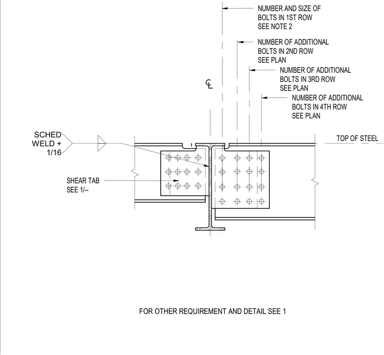
A single-plate shear tab connects the supported steel beam web to the supporting member web using multi-row bolting governed by the structural schedule and plan requirements. The shear tab plate is welded to the support column or girder with a weld size scaled per schedule plus one-sixteenth of an inch. Bolt counts and sizes for each vertical row are determined per engineering notes and framing plans relative to the member centerline and top of steel elevation.
SHEAR TAB SEE 1/-- TOP OF STEEL NUMBER AND SIZE OF BOLTS IN 1ST ROW SEE NOTE 2 NUMBER OF ADDITIONAL BOLTS IN 2ND ROW SEE PLAN SCHED WELD + 1/16 NUMBER OF ADDITIONAL BOLTS IN 3RD ROW SEE PLAN FOR OTHER REQUIREMENT AND DETAIL SEE 1 NUMBER OF ADDITIONAL BOLTS IN 4TH ROW SEE PLAN
Members view this detail in full resolution, download the CAD files (SVG, PDF), and can adapt it in the built-in CAD editor — export DXF, DWG, or PDF.
Start membership