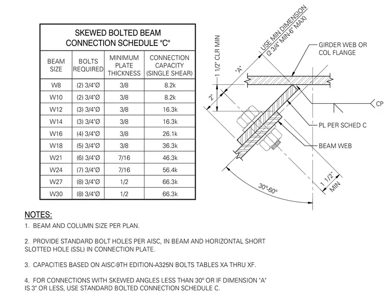
This structural detail and schedule specifies skewed bolted beam connections for wide flange beam sizes ranging from W8 to W30. The assembly includes a connection plate welded or attached to a girder web or column flange, with the skewed beam web bolted to the connection plate using three-quarter-inch diameter A325N bolts in standard and horizontal short slotted holes. Design capacities range from 8.2k to 66.3k in single shear based on AISC 9th edition tables for skewed angles between thirty and sixty degrees. Minimum plate thicknesses vary from three-eighths to one-half inch depending on the beam size. General notes require standard bolt holes per AISC and reference standard connection schedules for skewed angles less than thirty degrees.
SKEWED BOLTED BEAM CONNECTION SCHEDULE "C" BEAM SIZE BOLTS REQUIRED MINIMUM PLATE THICKNESS CONNECTION CAPACITY (SINGLE SHEAR) W8 W10 W12 W14 W16 W18 W21 W24 W27 W30 (2) 3/4"Ø (2) 3/4"Ø (3) 3/4"Ø (3) 3/4"Ø (4) 3/4"Ø (5) 3/4"Ø (6) 3/4"Ø (7) 3/4"Ø (8) 3/4"Ø (8) 3/4"Ø 8.2k 8.2k 16.3k 16.3k 26.1k 36.3k 46.3k 56.4k 66.3k 66.3k 3/8 3/8 3/8 3/8 3/8 3/8 7/16 7/16 1/2 1/2 NOTES: 1. BEAM AND COLUMN SIZE PER PLAN. 2. PROVIDE STANDARD BOLT HOLES PER AISC, IN BEAM AND HORIZONTAL SHORT SLOTTED HOLE (SSL) IN CONNECTION PLATE. 3. CAPACITIES BASED ON AISC-9TH EDITION-A325N BOLTS TABLES XA THRU XF. 4. FOR CONNECTIONS WITH SKEWED ANGLES LESS THAN 30º OR IF DIMENSION "A" IS 3" OR LESS, USE STANDARD BOLTED CONNECTION SCHEDULE C. BEAM WEB PL PER SCHED C GIRDER WEB OR COL FLANGE 1 1/2" CLR MIN USE MIN DIMENSION (2 3/4" MIN-6" MAX) 30º-60º CP MIN 1 1/2" "A" 2"
Members view this detail in full resolution, download the CAD files (SVG, PDF), and can adapt it in the built-in CAD editor — export DXF, DWG, or PDF.
Start membership