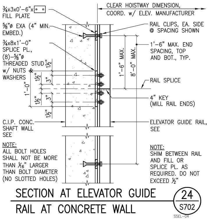
An elevator guide rail is anchored to a cast-in-place concrete shaft wall using expansion anchors and threaded studs. A three-quarter inch by three-inch by one-foot six-inch fill plate spaces the assembly from the concrete wall, secured by five-eighth inch diameter expansion anchors with a four-inch minimum embedment. The rail splice is detailed with a three-quarter inch by eight-inch by one-foot zero-inch splice plate fastened by eight five-eighth inch diameter threaded studs with nuts and washers. A four-inch key is milled into the rail ends at the splice location. Rail clips are installed on each side at the spacing shown, maintaining a one-foot six-inch maximum end spacing at the top and bottom typically, and an eight-foot zero-inch maximum intermediate spacing. Shims are placed between the rail and the fill or splice plate as required, not to exceed one-half inch. All bolt holes shall not be more than one-sixteenth inch larger than the bolt diameter with no slotted holes permitted.
Members view this detail in full resolution, download the CAD files (SVG, PDF), and can adapt it in the built-in CAD editor — export DXF, DWG, or PDF.
Start membership