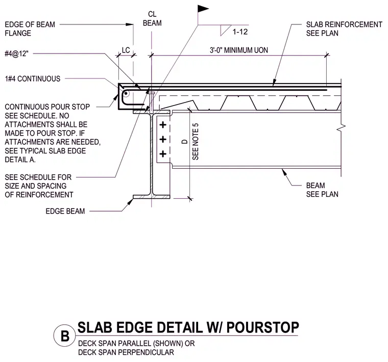
A concrete floor slab bears on a structural steel edge beam with a metal deck spanning either parallel or perpendicular to the beam. A continuous pour stop is attached at the slab edge, accompanied by a continuous number four rebar and number four reinforcing bars spaced at twelve inches on center. Slab reinforcement sizing and spacing follow the structural plans, and the assembly maintains a three-foot minimum dimension unless noted otherwise. Attachments to the pour stop are prohibited unless directed to standard detail alternatives.
#4@12" 1#4 CONTINUOUS EDGE OF BEAM FLANGE DECK SPAN PARALLEL (SHOWN) OR DECK SPAN PERPENDICULAR BEAM SEE PLAN SEE SCHEDULE FOR SIZE AND SPACING OF REINFORCEMENT CONTINUOUS POUR STOP SEE SCHEDULE. NO ATTACHMENTS SHALL BE MADE TO POUR STOP. IF ATTACHMENTS ARE NEEDED, SEE TYPICAL SLAB EDGE DETAIL A. SEE NOTE 5 D LC 3'-0" MINIMUM UON 1-12 SLAB REINFORCEMENT SEE PLAN EDGE BEAM CL BEAM B SLAB EDGE DETAIL W/ POURSTOP #4@12" 1#4 CONTINUOUS EDGE OF BEAM FLANGE DECK SPAN PARALLEL (SHOWN) OR DECK SPAN PERPENDICULAR BEAM SEE PLAN SEE SCHEDULE FOR SIZE AND SPACING OF REINFORCEMENT CONTINUOUS POUR STOP SEE SCHEDULE. NO ATTACHMENTS SHALL BE MADE TO POUR STOP. IF ATTACHMENTS ARE NEEDED, SEE TYPICAL SLAB EDGE DETAIL A. SEE NOTE 5 D LC 3'-0" MINIMUM UON 1-12 SLAB REINFORCEMENT SEE PLAN EDGE BEAM CL BEAM B SLAB EDGE DETAIL W/ POURSTOP
Members view this detail in full resolution, download the CAD files (SVG, PDF), and can adapt it in the built-in CAD editor — export DXF, DWG, or PDF.
Start membership