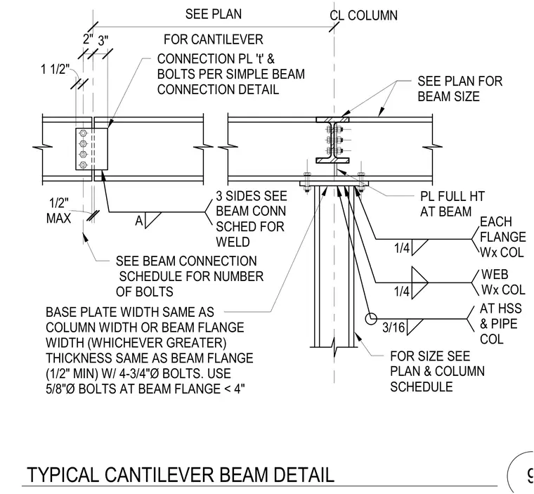
A cantilever beam connects to a wide-flange column using connection plates and bolts sized per the beam connection schedule, with a full-height plate at the beam-to-column joint welded on three sides. The base plate matches the column width or beam flange width with a minimum one-half inch thickness, secured by four three-quarter inch diameter anchor bolts, or five-eighth inch diameter bolts when the beam flange is less than four inches. Additional connections use one-quarter inch fillet welds at each flange and web for wide-flange columns, and three-sixteenth inch fillet welds for hollow structural section and pipe columns. A maximum gap of one-half inch is maintained at the cantilever joint. Member sizes and additional connection details are coordinated with the structural plans and schedules.
PL FULL HT AT BEAM CONNECTION PL 't' & BOLTS PER SIMPLE BEAM CONNECTION DETAIL EACH FLANGE Wx COL CL COLUMN SEE PLAN FOR BEAM SIZE 3 SIDES SEE BEAM CONN SCHED FOR WELD SEE BEAM CONNECTION SCHEDULE FOR NUMBER OF BOLTS FOR SIZE SEE PLAN & COLUMN SCHEDULE 1/4 2" 1/4 A FOR CANTILEVER SEE PLAN BASE PLATE WIDTH SAME AS COLUMN WIDTH OR BEAM FLANGE WIDTH (WHICHEVER GREATER) THICKNESS SAME AS BEAM FLANGE (1/2" MIN) W/ 4-3/4"Ø BOLTS. USE 5/8"Ø BOLTS AT BEAM FLANGE < 4" MAX 1/2" AT HSS & PIPE COL 3/16 1 1/2" 3" WEB Wx COL TYPICAL CANTILEVER BEAM DETAIL 9
Members view this detail in full resolution, download the CAD files (SVG, PDF), and can adapt it in the built-in CAD editor — export DXF, DWG, or PDF.
Start membership