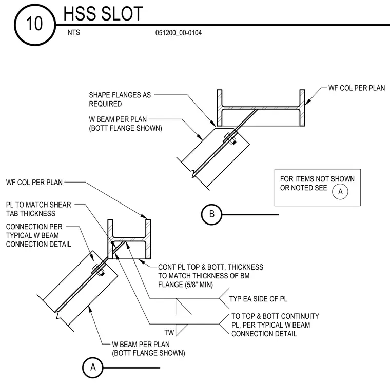
A wide-flange beam is framed at an angle into a wide-flange column per plan, with its bottom flange shown and the beam flanges shaped as required to fit the geometry. Continuous plates matching the thickness of the beam flange with a five-eighths inch minimum are provided on both the top and bottom of the connection on each side of the plate. A connection per the typical wide-flange beam connection detail is used, with plate thicknesses matching the shear tab thickness. For items not shown or noted, refer to detail A.
W BEAM PER PLAN (BOTT FLANGE SHOWN) WF COL PER PLAN CONT PL TOP & BOTT, THICKNESS TO MATCH THICKNESS OF BM FLANGE (5/8" MIN) TYP EA SIDE OF PL TW A WF COL PER PLAN W BEAM PER PLAN (BOTT FLANGE SHOWN) B FOR ITEMS NOT SHOWN OR NOTED SEE A CONNECTION PER TYPICAL W BEAM CONNECTION DETAIL TO TOP & BOTT CONTINUITY PL, PER TYPICAL W BEAM CONNECTION DETAIL PL TO MATCH SHEAR TAB THICKNESS SHAPE FLANGES AS REQUIRED NTS HSS SLOT 10 051200_00-0104
Members view this detail in full resolution, download the CAD files (SVG, PDF), and can adapt it in the built-in CAD editor — export DXF, DWG, or PDF.
Start membership