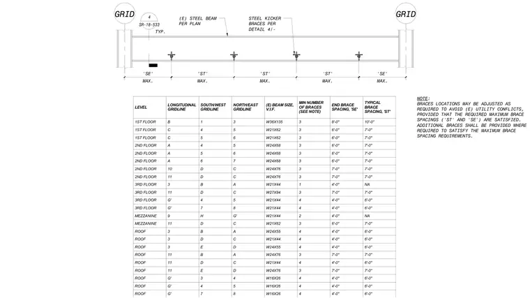
Existing steel beams are strengthened using steel kicker braces installed at maximum end brace spacings ('SE') and typical brace spacings ('ST') as indicated in the accompanying schedule. Brace locations may be adjusted to avoid existing utility conflicts provided the required maximum spacings are satisfied. Additional braces are provided where required to meet maximum spacing requirements.
LEVEL LONGITUDINAL GRIDLINE SOUTH/WEST GRIDLINE NORTH/EAST GRIDLINE (E) BEAM SIZE, V.I.F. MIN NUMBER OF BRACES (SEE NOTE) END BRACE SPACING, 'SE' TYPICAL BRACE SPACING, 'ST' 1ST FLOOR B 1 3 W36X135 3 8'-0'' 10'-0'' 1ST FLOOR C 4 5 W21X62 3 6'-0'' 7'-0'' 1ST FLOOR C 5 6 W21X62 3 6'-0'' 7'-0'' 2ND FLOOR A 4 5 W24X68 3 6'-0'' 7'-0'' 2ND FLOOR A 5 6 W24X68 3 6'-0'' 7'-0'' 2ND FLOOR A 6 7 W24X68 3 6'-0'' 7'-0'' 2ND FLOOR 10 D C W24X76 3 7'-0'' 7'-0'' 2ND FLOOR 11 D C W24X76 3 7'-0'' 7'-0'' 3RD FLOOR 3 B A W21X44 1 4'-0'' NA 3RD FLOOR 11 D C W27X84 3 7'-0'' 7'-0'' 3RD FLOOR G' 4 5 W21X44 4 4'-0'' 6'-0'' 3RD FLOOR G' 7 8 W21X44 4 4'-0'' 6'-0'' MEZZANINE 9 H G' W21X44 2 4'-0'' NA MEZZANINE 11 D C W21X62 3 6'-0'' 7'-0'' ROOF 3 B A W24X55 4 4'-0'' 6'-0'' ROOF 3 D C W21X44 4 4'-0'' 6'-0'' ROOF 3 E D W24X55 4 4'-0'' 6'-0'' ROOF 11 B A W24X76 3 7'-0'' 7'-0'' ROOF 11 D C W21X44 4 4'-0'' 6'-0'' ROOF 11 E D W24X76 3 7'-0'' 7'-0'' ROOF G' 3 4 W16X26 4 4'-0'' 6'-0'' ROOF G' 4 5 W16X26 4 4'-0'' 6'-0'' ROOF G' 7 8 W16X26 4 4'-0'' 6'-0'' NOTE: BRACES LOCATIONS MAY BE ADJUSTED AS REQUIRED TO AVOID (E) UTILITY CONFLICTS, PROVIDED THAT THE REQUIRED MAXIMUM BRACE SPACINGS ('ST' AND 'SE') ARE SATISFIED. ADDITIONAL BRACES SHALL BE PROVIDED WHERE REQUIRED TO SATISFY THE MAXIMUM BRACE SPACING REQUIREMENTS. GRID (E) STEEL BEAM PER PLAN GRID 4 SR-18-533 TYP. MAX. 'SE' MAX. 'ST' MAX. 'ST' MAX. 'ST' MAX. 'SE' STEEL KICKER BRACES PER DETAIL 4/-
Members view this detail in full resolution, download the CAD files (SVG, PDF), and can adapt it in the built-in CAD editor — export DXF, DWG, or PDF.
Start membership