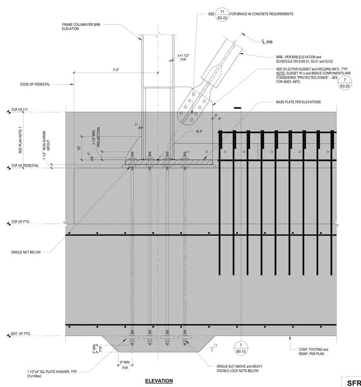
A buckling-restrained brace and frame column connect and anchor to a reinforced concrete continuous footing and pedestal. The steel frame column is supported on a base plate with a one-and-a-half-inch non-shrink grout layer over the concrete pedestal. Anchor rods extend through the footing and feature square plate washers and single nuts below, with single nuts above and heavy double lock nuts below at the anchorage zone. A gusset plate connects the buckling-restrained brace to the column and foundation system, designated as a protected zone requiring specific welding and detailing per referenced structural sheets. Reinforcing bars and continuous footing details are provided per plan, incorporating specific clearances and edge distances.
ELEVATION SFRS BOT. OF FTG. TOP OF FTG. TOP OF F.F. FRAME COLUMN PER BRB ELEVATION TYP. 6" MIN. 3" TYP. 3" MIN. 1 1 TYP. k+1 1/2" 1" 1" 10" W.P. GROUT 1 1/2" NON-SHRINK SEE S3.22 FOR GUSSET and WELDING INFO., TYP. NOTE: GUSSET PL's and BRACE COMPONENTS ARE CONSIDERED "PROTECTED ZONES" - SEE FOR ADD'L INFO. BASE PLATE PER ELEVATIONS BRB - PER BRB ELEVATION and SCHEDULE ON S-B3.01, S3.21 and S3.22 BRB CONT. FOOTING and REINF. PER PLAN SINGLE NUT BELOW PROJECTION 3 1/2" MIN. SINGLE NUT ABOVE and HEAVY DOUBLE LOCK NUTS BELOW SEE PLAN NOTE 7 7 S3.22 7 S0.12 TOP OF PEDESTAL EDGE OF PEDESTAL 3'-0" SEE FOR BRACE IN CONCRETE REQUIREMENTS 11 S3.22 1 1/2"x6" SQ. PLATE WASHER, TYP. (Fy=50ksi)
Members view this detail in full resolution, download the CAD files (SVG, PDF), and can adapt it in the built-in CAD editor — export DXF, DWG, or PDF.
Start membership