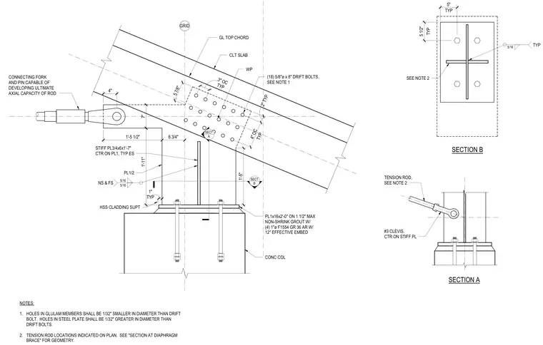
A heavy timber truss end connection bears on a concrete column. The glulam top chord and cross-laminated timber slab connect to a 1/2-inch steel plate via eighteen 5/8-inch diameter by 8-inch drift bolts spaced at 3 inches on center. A connecting fork and pin assembly ties into a tension rod, transferring axial loads to a vertical stiffener plate centered on the main gusset. The assembly anchors to the concrete column via a 1-inch by 16-inch by 2-foot base plate set on a maximum 1 1/2 inches of non-shrink grout and secured by four 1-inch diameter F1554 Grade 36 anchor rods with a 12-inch effective embedment. Fillet welds of 5/16-inch size connect the plates as indicated, and an HSS cladding support ties into the base assembly.
SECT A B SECT GRID NOTES: 1. HOLES IN GLULAM MEMBERS SHALL BE 1/32" SMALLER IN DIAMETER THAN DRIFT BOLT. HOLES IN STEEL PLATE SHALL BE 1/32" GREATER IN DIAMETER THAN DRIFT BOLTS. 2. TENSION ROD LOCATIONS INDICATED ON PLAN. SEE "SECTION AT DIAPHRAGM BRACE" FOR GEOMETRY. 7" TYP 1" 1'-11" 1'-5 1/2" 6 3/4" 1'-5" 5 7/8" 4" CONNECTING FORK AND PIN CAPABLE OF DEVELOPING ULTIMATE AXIAL CAPACITY OF ROD CLT SLAB GL TOP CHORD 2" TYP TYP 4" OC WP (18) 5/8"ø x 8" DRIFT BOLTS. SEE NOTE 1 TYP 3" OC STIFF PL3/4x6x1'-7" CTR ON PL1, TYP ES NS & FS 5/16 5/16 PL1/2 PL1x16x2'-0" ON 1 1/2" MAX NON-SHRINK GROUT W/ (4) 1"ø F1554 GR 36 AR W/ 12" EFFECTIVE EMBED CONC COL HSS CLADDING SUPT SECTION A TENSION ROD, SEE NOTE 2 #3 CLEVIS, CTR ON STIFF PL SECTION B SEE NOTE 2 TYP 5 1/2" TYP 5" TYP 5/16
Members view this detail in full resolution, download the CAD files (SVG, PDF), and can adapt it in the built-in CAD editor — export DXF, DWG, or PDF.
Start membership