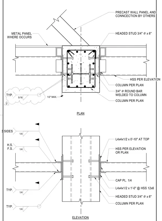
A concrete column per plan with an embedded structural steel shape serves as the primary support, featuring three-quarter-inch diameter by six-inch headed studs welded to its faces. Hollow structural section members frame into the column sides, tied with a quarter-inch cap plate and supporting angles including L4x4x1/2 by zero-feet-ten-inches at the top and L4x4x1/2 by one-foot-zero-inches at the HSS 12x6. A three-quarter-inch diameter round bar is welded to the column to interface with adjacent assemblies. Precast wall panels and metal panels occur at the exterior boundary with a half-inch maximum joint clearance. Fillet welds of quarter-inch and five-sixteenth-inch sizes secure the connection plates and angles as specified.
PLAN PRECAST WALL PANEL AND CONNCECTION BY OTHERS COLUMN PER PLAN HSS PER ELEVATION OR PLAN CAP PL. 1/4 L4x4x1/2 x 1'-0" @ HSS 12x6 HEADED STUD 3/4" ⌀ x 6" COLUMN PER PLAN METAL PANEL WHERE OCCURS 1/4 TYP. 1/4 TYP. 1/2" MAX. HSS PER ELEVATION 3/4" ⌀ ROUND BAR WELDED TO COLUMN ELEVATION L4x4x1/2 x 0'-10" AT TOP 1/4 3 SIDES 1/4 H.S. F.S. COLUMN PER PLAN HEADED STUD 3/4" ⌀ x 6" 5/16 TYP. 2
Members view this detail in full resolution, download the CAD files (SVG, PDF), and can adapt it in the built-in CAD editor — export DXF, DWG, or PDF.
Start membership