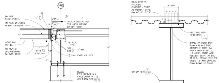
A concrete beam frames into a structural steel column utilizing three-quarter-inch by six-inch by nine-and-a-quarter-inch plates welded to each side with five-sixteenths-inch fillet welds. Four number-six bars five feet long align with the beam top reinforcement, while three number-seven bars five feet long are located between the beam bottom reinforcement. Four number-four ties spaced at one-and-a-half inches on center enclose the dowels, with four half-inch deformed bar anchors featuring one-hundred-eighty-degree standard hooks wrapped around the beam top reinforcement. A composite metal deck bears on the supporting steel member, secured with three-quarter-inch by four-and-a-half-inch shear studs placed in groups at eight inches from each end and twenty-four inches on center, and welded per plan specifications.
GRID NOTE: FOR DETAILS & CALLOUTS IN COMMON SEE 3 S52-02 2" " d" TYP. 1½" CLR. 3" 5 S52-02 5/16 5/16 TYP. (4) 1/2"& DBA W/ 180° STD HOOK AROUND BM TOP REINF. BM TOP REINF. PER EL (4) #6x5'-0" ALIGN W/ BM TOP REINF. CONC. BM PER EL. (3) #7x5'-0" LOCATE BTWN BM BOT. REINF. 5 3/4"x6"x9¼" EA. SIDE 4 1 / 2" 1 1 /2" 1" (4) #4 @ 1½" O.C. 1/2 3 3 3" 3" 3" 3" 14" MIN. DECK MFR TO PROVIDE CLOSURE - STRIP AS REQ'D - SAME GA. AS MTL DECK WELD MTL DECK TO BM PER 1 S51-00 3/4"&x4½" STUDS PER PLAN - PLACE STUD GROUPS 8" FROM EA. END & THEN @ 24" O.C. - IF ADD'L STUDS ARE NEEDED: START AT END OF BM & SPACE BTWN (E) STUDS - 6" MIN. SPACING BTWN ROWS OF STUDS B.U. BM PER 1 S52-02
Members view this detail in full resolution, download the CAD files (SVG, PDF), and can adapt it in the built-in CAD editor — export DXF, DWG, or PDF.
Start membership