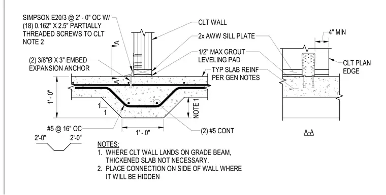
A cross-laminated timber wall bears on an asphalt-treated wood sill plate over a concrete slab. A half-inch maximum grout leveling pad sits beneath the sill plate atop the concrete slab. The CLT wall is anchored to the slab using Simpson E20/3 brackets spaced at two feet on center, secured with eighteen 0.162-inch by 2.5-inch partially threaded screws into the CLT and two 3/8-inch diameter by 3-inch embedded expansion anchors into the concrete. The concrete slab features a thickened drop section reinforced with two continuous number 5 rebars and number 5 rebars spaced at 16 inches on center. Where the CLT wall lands on a grade beam, the thickened slab is omitted. The connection is specified to be placed on the side of the wall where it remains hidden.
A A TYP SLAB REINF PER GEN NOTES 1 1 (2) #5 CONT 1' - 0" 1' - 0" CLT WALL #5 @ 16" OC 2'-0" 2'-0" SIMPSON E20/3 @ 2' - 0" OC W/ (18) 0.162" X 2.5" PARTIALLY THREADED SCREWS TO CLT NOTE 2 1/2" MAX GROUT LEVELING PAD (2) 3/8"Ø X 3" EMBED EXPANSION ANCHOR 2x AWW SILL PLATE 4" MIN CLT PLAN EDGE A-A NOTES: 1. WHERE CLT WALL LANDS ON GRADE BEAM, THICKENED SLAB NOT NECESSARY. 2. PLACE CONNECTION ON SIDE OF WALL WHERE IT WILL BE HIDDEN NOTE 1
Members view this detail in full resolution, download the CAD files (SVG, PDF), and can adapt it in the built-in CAD editor — export DXF, DWG, or PDF.
Start membership