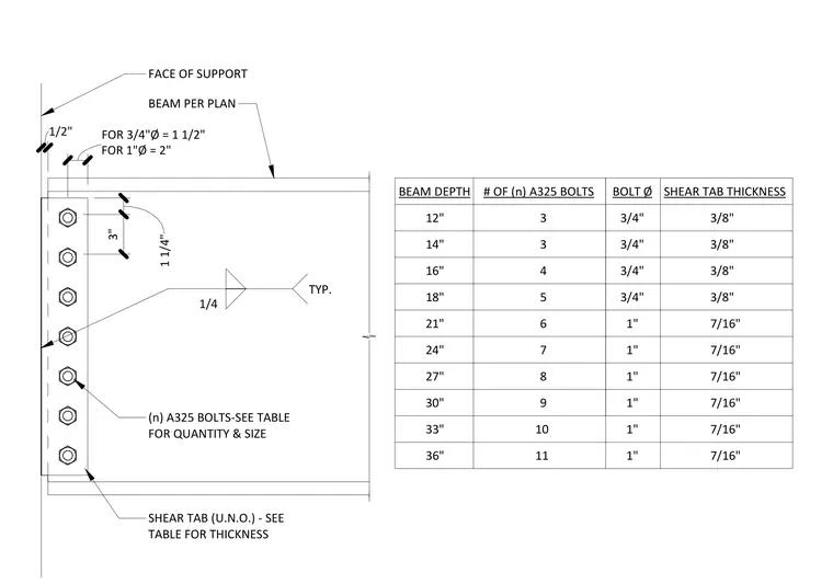
This detail defines the standard configuration for a single plate shear tab connection between a beam and a support member. The shear tab is welded to the face of the support with a 1/4 inch fillet weld, typical. The beam is connected to the shear tab using a specified quantity of A325 bolts, with the bolt diameter and shear tab thickness determined by the beam depth as outlined in the accompanying table. Bolt spacing is set at 3 inches on center, with a 1 1/4 inch edge distance for 3/4 inch diameter bolts and a 2 inch edge distance for 1 inch diameter bolts. The face of the support is maintained at a 1/2 inch clearance from the beam end.
BEAM DEPTH # OF (n) A325 BOLTS 12" 3 14" 3 16" 4 18" 5 21" 6 24" 7 27" 8 30" 9 FACE OF SUPPORT BEAM PER PLAN SHEAR TAB (U.N.O.) - SEE TABLE FOR THICKNESS (n) A325 BOLTS-SEE TABLE FOR QUANTITY & SIZE 1/2" 1/4 TYP. BOLT Ø SHEAR TAB THICKNESS 3/8" 3/8" 3/8" 3/8" 7/16" 10 11 33" 36" 3/4" 3/4" 3/4" 3/4" 1" 1" 1" 1" 1" 1" FOR 1"Ø = 2" FOR 3" 1 1/4" FOR 3/4"Ø = 1 1/2" 7/16" 7/16" 7/16" 7/16" 7/16"
Members view this detail in full resolution, download the CAD files (SVG, PDF), and can adapt it in the built-in CAD editor — export DXF, DWG, or PDF.
Start membership