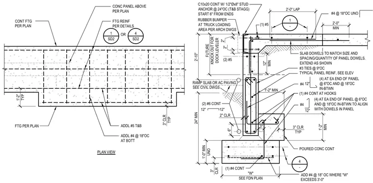
A continuous concrete footing supports a concrete wall with a dock leveler knockout. The footing features bottom continuous reinforcing bars, additional transverse bars spaced eighteen inches on center, and a standard three-inch concrete clearance. The wall incorporates vertical reinforcing, horizontal continuous bars, and number three ties at nine inches on center. A continuous channel embedded at the top edge secures a rubber bumper, with slab dowels tying into the adjacent ramp slab or asphalt paving.
PLAN VIEW CONT FTG PER PLAN CONC PANEL ABOVE PER PLAN FTG REINF PER DETAILS 1'-2" TYP FTG PER PLAN ADDL #5 T&B 3" CLR TYP ADDL #4 @ 18"OC AT BOTT 1 SD2 4 SD2 OR RAMP SLAB OR AC PAVING SEE CIVIL DWGS 3" CLR TYP (1) #4 CONT AT HOOKS POURED CONC CONT 1'-2" MIN 12" #4 12" 1'-2" MIN 1'-0" MIN UNO 3" CLR 2" CLR 6" 3" (4) AT EA END OF PANEL @ 6"OC AND @ 18"OC IN-BTWN TO ALIGN WITH DOWELS IN PANEL #4 (4) AT EA END OF PANEL @ 6"OC AND @ 18"OC IN-BTWN 1 - 2'-0" LAP 2'-0" MIN SLAB DOWELS TO MATCH SIZE AND SPACING/QUANTITY OF PANEL DOWELS. EXTEND AS SHOWN #4 @ 18"OC UNO 12" MIN ADD #4 @ 18" OC WHERE "W" EXCEEDS 3'-0" 24" MIN 2'-10" FUTURE KNOCK OUT FOR DOCK LEVELER (2) #5 2" 2" C10x20 CONT W/ 1/2 "Øx8" STUD ANCHOR @ 24"OC (T&B STAGG) START 6" FROM ENDS RUBBER BUMPER AT TRUCK LOADING AREA PER ARCH DWGS (1) #5 (2) #6 CONT 12" 12" #3 TIES @ 9"OC TYPICAL PANEL REINF, SEE ELEV "W" SEE FDN PLAN (1) #4 CONT 4 -
Members view this detail in full resolution, download the CAD files (SVG, PDF), and can adapt it in the built-in CAD editor — export DXF, DWG, or PDF.
Start membership