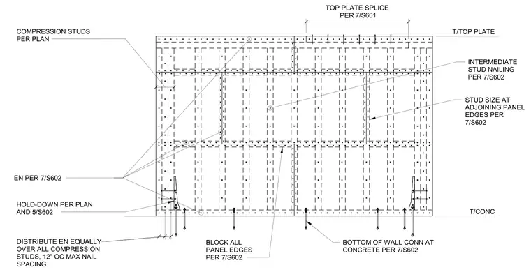
This elevation details the fastening requirements for a wood-framed shear wall panel assembly. Compression studs are located per plan, with end nailing requirements specified per detail 7/S602. The top plate splice is detailed per 7/S601, while intermediate stud nailing and stud sizes at adjoining panel edges are governed by 7/S602. Hold-downs are installed per plan and 5/S602, with bottom of wall connections to the concrete foundation specified per 7/S602. All panel edges are blocked per 7/S602, and end nailing is distributed equally over all compression studs at a maximum 12-inch on-center nail spacing.
Members view this detail in full resolution, download the CAD files (SVG, PDF), and can adapt it in the built-in CAD editor — export DXF, DWG, or PDF.
Start membership