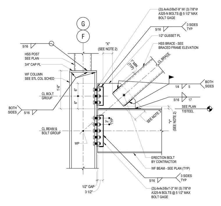
A wide-flange column connects to a wide-flange beam and a hollow structural section brace utilizing a half-inch gusset plate. The HSS brace is framed with a one-inch minimum clearance and utilizes double angles measuring four by four by three-eighths inches with three seven-eighths-inch diameter A325-N bolts at five-and-a-half-inch maximum bolt gauge. The wide-flange beam connects via double angles measuring four by four by three-eighths inches by one foot three inches with five seven-eighths-inch diameter A325-N bolts. A three-quarter-inch cap plate is welded to the top of the wide-flange column, supporting an HSS post above. Five-sixteenths-inch fillet welds are specified on three sides typically, with additional welds on both sides as indicated by the symbols.
F T/STEEL SEE PLAN CL BEAM & BOLT GROUP WP HSS BRACE - SEE BRACED FRAME ELEVATION CL BOLT GROUP WF COLUMN SEE STL COL SCHED 5/16 3 SIDES TYP 5/16 3 SIDES TYP WF BEAM - SEE PLAN (TYP) "Y" (SEE NOTE 2) 6" 6" 5/16 17 1/4 5 BOTH SIDES ERECTION BOLT BY CONTRACTOR TYP 3" (2)L4x4x3/8x1'-3" W/ (5) 7/8" ⌀ A325-N BOLTS @ 5 1/2" MAX BOLT GAGE 1/2" GAP 3 1/2" 1/2" GUSSET PL (2)L4x4x3/8x0'-9" W/ (3) 7/8" ⌀ A325-N BOLTS @ 5 1/2" MAX BOLT GAGE 1'-6" 3/4" CAP PL HSS POST SEE PLAN 5/16 BOTH SIDES G 5/16 CL BRACE (TYP) 1" MIN SEE NOTE 3 (SEE NOTE 2) "X"
Members view this detail in full resolution, download the CAD files (SVG, PDF), and can adapt it in the built-in CAD editor — export DXF, DWG, or PDF.
Start membership