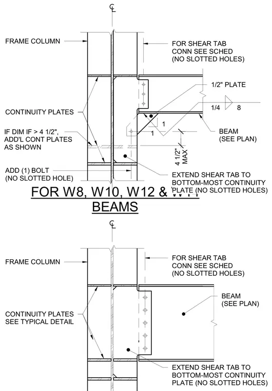
The connection consists of a structural steel beam framing into a frame column using a one-half-inch thick shear tab welded to the column flange. The shear tab is extended down to meet the bottom-most continuity plate, utilizing unslotted holes throughout. Additional continuity plates are installed inside the column web matching the beam flanges, with extra plates added if the dimension exceeds four and one-half inches. An additional bolt is provided with no slotted hole in the extended region. Fillet welds of one-quarter inch size connect the shear tab and plates as indicated.
FOR W8, W10, W12 & W14 BEAMS FRAME COLUMN BEAM (SEE PLAN) 1 1 EXTEND SHEAR TAB TO BOTTOM-MOST CONTINUITY PLATE (NO SLOTTED HOLES) ADD (1) BOLT (NO SLOTTED HOLE) BEAM (SEE PLAN) 1/2" PLATE CONTINUITY PLATES FRAME COLUMN FOR SHEAR TAB CONN SEE SCHED (NO SLOTTED HOLES) CONTINUITY PLATES SEE TYPICAL DETAIL 1/4 8 EXTEND SHEAR TAB TO BOTTOM-MOST CONTINUITY PLATE (NO SLOTTED HOLES) FOR SHEAR TAB CONN SEE SCHED (NO SLOTTED HOLES) MAX 4 1/2" IF DIM IF > 4 1/2", ADD'L CONT PLATES AS SHOWN
Members view this detail in full resolution, download the CAD files (SVG, PDF), and can adapt it in the built-in CAD editor — export DXF, DWG, or PDF.
Start membership