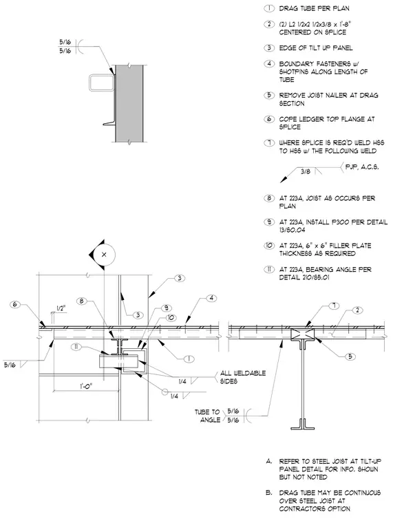
A hollow structural section drag tube framing connection occurs at a tilt-up concrete wall panel. The assembly features a drag tube per plan connected to a steel joist bearing on an angle with a filler plate. A splice condition in the drag tube uses a pair of 2-1/2 by 2-1/2 by 3/8-inch angles centered on the splice and welded with specified fillet and partial joint penetration welds. Boundary fasteners with shotpins secure the deck along the length of the tube, and the ledger top flange is coped at the splice location.
X 1'-0" 1/2" 4 1 3 4 5 6 2 A. 3 3 5 2 1 7 7 PJP, A.C.S. 3/8 6 B. REFER TO STEEL JOIST AT TILT-UP PANEL DETAIL FOR INFO. SHOWN BUT NOT NOTED DRAG TUBE MAY BE CONTINUOUS OVER STEEL JOIST AT CONTRACTORS OPTION DRAG TUBE PER PLAN EDGE OF TILT UP PANEL REMOVE JOIST NAILER AT DRAG SECTION WHERE SPLICE IS REQ'D WELD HSS TO HSS w/ THE FOLLOWING WELD (2) L2 1/2x2 1/2x3/8 x 1'-8" CENTERED ON SPLICE BOUNDARY FASTENERS w/ SHOTPINS ALONG LENGTH OF TUBE COPE LEDGER TOP FLANGE AT SPLICE 5/16 5/16 5/16 5/16 5/16 TUBE TO ANGLE 8 AT 223A, JOIST AS OCCURS PER PLAN 9 AT 223A, INSTALL P300 PER DETAIL 13/S0.04 10 AT 223A, 6" x 6" FILLER PLATE THICKNESS AS REQUIRED 11 AT 223A, BEARING ANGLE PER DETAIL 210/S5.01 9 10 1/4 1/4 ALL WELDABLE SIDES 11 8
Members view this detail in full resolution, download the CAD files (SVG, PDF), and can adapt it in the built-in CAD editor — export DXF, DWG, or PDF.
Start membership