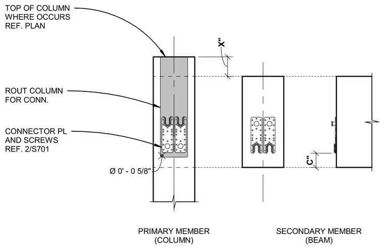
A secondary beam connects to a primary column member using connector plates and screws. The primary column is routed to accommodate the connector plate assembly. Dimensions indicate vertical offsets and position relative to the top of the column as referenced in the structural plans.
Ø 0' - 0 5/8" C" X" PRIMARY MEMBER (COLUMN) SECONDARY MEMBER (BEAM) TOP OF COLUMN WHERE OCCURS REF. PLAN ROUT COLUMN FOR CONN. CONNECTOR PL AND SCREWS REF. 2/S701
Members view this detail in full resolution, download the CAD files (SVG, PDF), and can adapt it in the built-in CAD editor — export DXF, DWG, or PDF.
Start membership