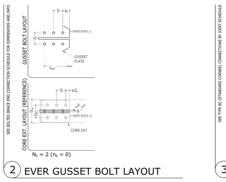
Standard bolt layout parameters for structural gusset plate connections. Key dimensional variables include bolt spacing, edge distances, and plate thicknesses for both the gusset plate and the core extension. The layout references standard corner connections and refers to the bolted brace end connection schedule for specific values.
3 SEE TYPE BC (STANDARD CORNER) CONNECTIONS BY JOINT SCHEDULE. CORE EXT. LAYOUT (REFERENCE) GUSSET BOLT LAYOUT 2 EVER GUSSET BOLT LAYOUT t gr t g Gc S e2 i b sc # INNER ROWS, nr i # INNER ROWS, n i CORE EXT. GUSSET PLATE G e i S L bh SEE BOLTED BRACE END CONNECTION SCHEDULE FOR DIMENSIONS AND INFO. N c = 2 (n o = 0)
Members view this detail in full resolution, download the CAD files (SVG, PDF), and can adapt it in the built-in CAD editor — export DXF, DWG, or PDF.
Start membership