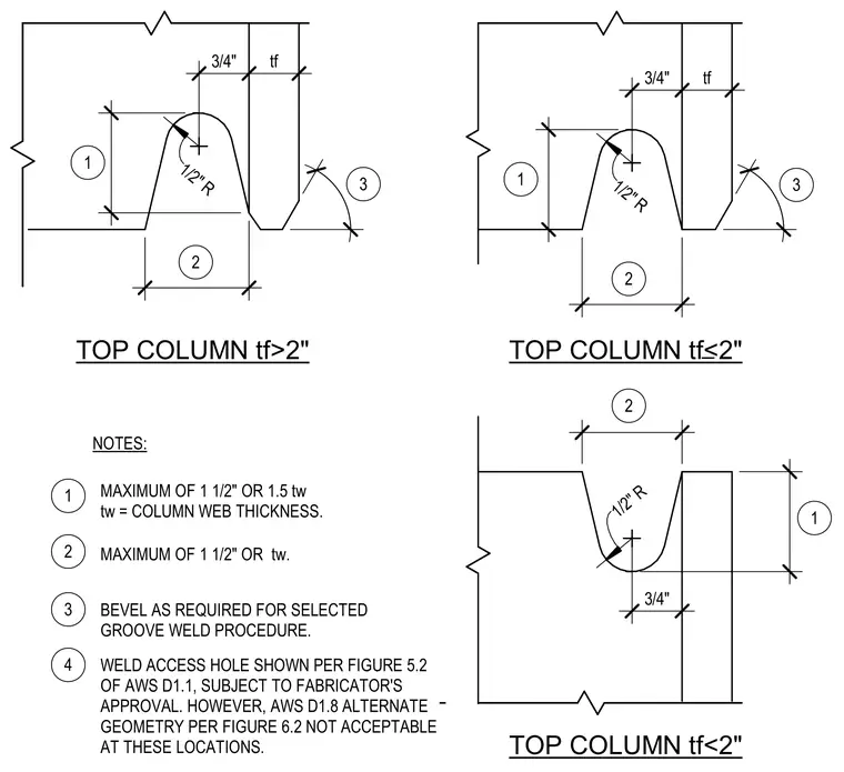
Three column weld access hole geometry configurations detail standard cutouts for heavy steel framing. Dimensions vary based on whether the column flange thickness is greater than or less than two inches, with a minimum half-inch radius at the root. Edges are beveled as required for the selected groove weld procedure. The weld access hole conforms to Figure 5.2 of AWS D1.1 subject to fabricator approval, while AWS D1.8 alternate geometry per Figure 6.2 is explicitly not acceptable at these locations.
3/4" tf 1/2" R 3 2 1 TOP COLUMN tf>2" 3/4" tf 1/2" R 3 2 1 TOP COLUMN tf<2" TOP COLUMN tf<2" 3/4" 1/2" R 1 2 1 2 3 4 NOTES: MAXIMUM OF 1 1/2" OR 1.5 tw tw = COLUMN WEB THICKNESS. MAXIMUM OF 1 1/2" OR tw. BEVEL AS REQUIRED FOR SELECTED GROOVE WELD PROCEDURE. WELD ACCESS HOLE SHOWN PER FIGURE 5.2 OF AWS D1.1, SUBJECT TO FABRICATOR'S APPROVAL. HOWEVER, AWS D1.8 ALTERNATE GEOMETRY PER FIGURE 6.2 NOT ACCEPTABLE AT THESE LOCATIONS.
Members view this detail in full resolution, download the CAD files (SVG, PDF), and can adapt it in the built-in CAD editor — export DXF, DWG, or PDF.
Start membership