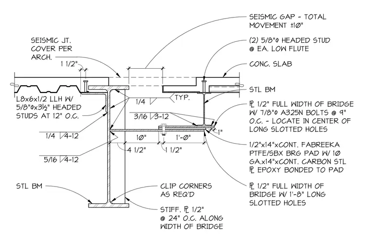
A bridge expansion joint and sliding bearing assembly connect structural steel beams supporting a concrete slab and metal deck. A seismic gap of ten inches total movement separates the two framing sections, accommodated by an architectural seismic joint cover. The sliding support consists of a continuous one-half-inch thick Fabreeka PTFE/SBX bearing pad with a ten-gauge continuous carbon steel plate epoxy bonded to the pad. This plate connects to a one-half-inch full-width bridge plate using seven-eighths-inch diameter A325N bolts spaced at nine inches on center, positioned in the center of one-foot-eight-inch long slotted holes. The supporting steel beam incorporates one-half-inch stiffener plates spaced at twenty-four inches on center along the bridge width, with clipped corners as required. Shear transfer is provided by five-eighths-inch diameter headed studs welded to the steel beams and metal deck.
4 1/2" 10" 1 1/2" 1'-0" 1 1/2" 10" SEISMIC GAP - TOTAL MOVEMENT ±10" SEISMIC JT. COVER PER ARCH. L8x6x1/2 LLH W/ 5/8"/x3½" HEADED STUDS AT 12" O.C. CLIP CORNERS AS REQ'D STL BM STIFF. 1/2" @ 24" O.C. ALONG WIDTH OF BRIDGE 1/2" FULL WIDTH OF BRIDGE W/ 1'-8" LONG SLOTTED HOLES 1/2"x14"xCONT. FABREEKA PTFE/SBX BRG PAD W/ 10 GA.x14"xCONT. CARBON STL EPOXY BONDED TO PAD 1/2" FULL WIDTH OF BRIDGE W/ 7/8"/ A325N BOLTS @ 9" O.C. - LOCATE IN CENTER OF LONG SLOTTED HOLES STL BM CONC. SLAB (2) 5/8"/ HEADED STUD @ EA. LOW FLUTE 1/4 4-12 5/16 4-12 1/4 TYP. 3/16 3-12 1"
Members view this detail in full resolution, download the CAD files (SVG, PDF), and can adapt it in the built-in CAD editor — export DXF, DWG, or PDF.
Start membership