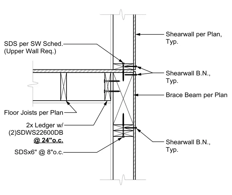
Floor joists are supported by a two-inch nominal lumber ledger fastened to a multi-stud or solid wood shear wall using structural wood screws spaced at twenty-four inches on center. The shear wall incorporates structural design screws per the shear wall schedule, along with blocking and boundary nailing typical throughout the assembly. A brace beam is integrated per plan to handle lateral load transfers at the floor level. The vertical shear wall panels align continuously across the floor intersection with specified edge nailing.
Shearwall per Plan, Typ. Shearwall B.N., Typ. SDS per SW Sched. (Upper Wall Req.) Brace Beam per Plan SDSx6" @ 8"o.c. Floor Joists per Plan 2x Ledger w/ (2)SDWS22600DB @ 24"o.c. Shearwall B.N., Typ.
Members view this detail in full resolution, download the CAD files (SVG, PDF), and can adapt it in the built-in CAD editor — export DXF, DWG, or PDF.
Start membership